


 Chinese
 Spanish
 Russian
 Portuguese
 French
 German
 Indonesian
 Thai
 Vietnamese
 Arabic
 Italian
 Turkish
 Polish
 Japanese


Radar nozzle geometry includes the clear bore, length, reducers and antenna position, not just the flange bolt pattern. A replacement instrument can fit mechanically while its lens sits higher inside a metal recess and sees a strong fixed reflection. Check the as-built section before changing signal-processing settings.
Radar Nozzle Geometry: Mark Two Different Reference Features
Use the exact instrument drawing to locate the measurement reference plane and the physical antenna face. They serve different checks: the reference plane defines distance and level scaling, while the face position determines how the antenna sits relative to the nozzle. Do not assume both coincide with the top of the flange.
| Dimension | Record | Why it matters |
|---|---|---|
| Bore | Actual internal opening, including lining and reducers. | Nominal connection size does not describe the clear microwave path. |
| Length | Total recess between the installed antenna and vessel opening. | Added adaptors can create a long reflecting passage. |
| Projection | Position of the antenna face relative to the inner opening. | The selected antenna must meet its approved mounting arrangement. |
| Air gap | Shortest distance from the measurement reference to the permitted surface. | The useful high-level region must remain outside the specified near limit. |
Also record welds, internal ledges and nearby structures. Photograph the accessible opening under the site's isolation procedure. For replacement work, compare the installed old and proposed new assemblies on the same section; an unchanged bolt circle can conceal a substantial change below it.
Compare Actual Antennas, Not Only Their Frequency
The METRAVON MV-RD12 uses a 32 mm PTFE lens with an 8-degree beam, while the MV-RD13 uses a 76 mm lens with a 3-degree beam. Both are 80 GHz liquid radars, but they do not have the same connection envelope or permitted installation geometry.
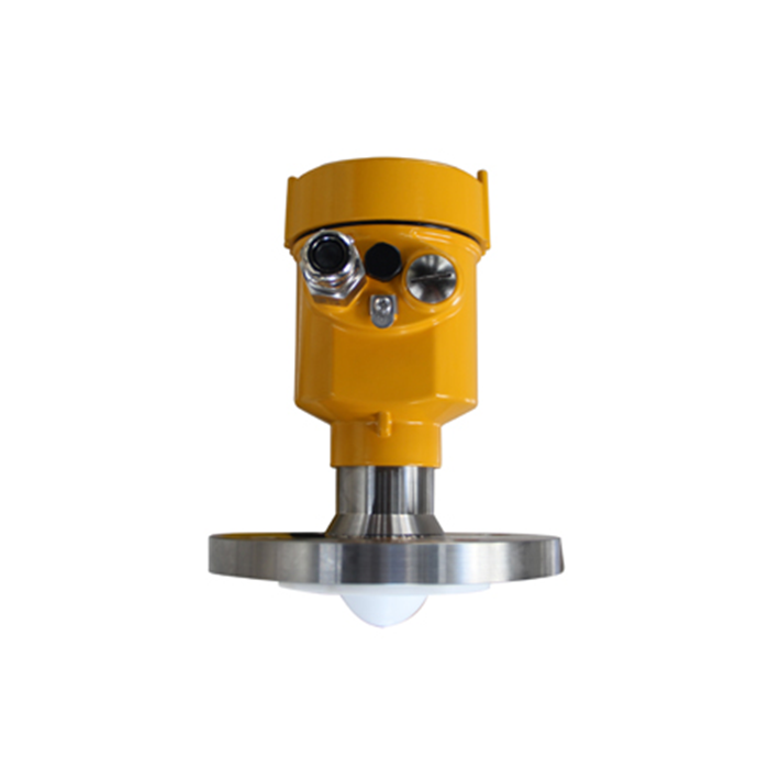
A smaller beam angle does not prove that a long narrow nozzle is acceptable. The signal interacts with nearby geometry before reaching the vessel surface. Obtain the permitted arrangement for the offered antenna and include any extension or adaptor in the approved assembly rather than inventing a universal length-to-diameter rule.
Check the Rest of the Path Before Accepting a Nozzle Change
Once the signal leaves the opening, it still needs a useful path to the lowest operating surface. Plot walls, braces, coils, agitators and the fill stream. A nozzle that is acceptable locally can place the beam over an obstruction farther down the tank.
Moving or extending a process connection also affects pressure containment, seals, thermal behaviour and maintenance. Use the plant's approved mechanical design and isolation procedures. Do not modify a pressure boundary or add an improvised antenna extension merely to clear a reflection.
Diagnose a Fixed Near Echo in Order
- Save the existing settings and raw echo information before applying suppression.
- Compare the suspected echo distance with measured nozzle and internal features.
- Observe the signal at independently known levels within the intended operating span, including the relevant high-level region.
- Correct unsuitable physical geometry through an approved design. Apply echo mapping only to identified fixed interference, then verify that the real surface remains detectable.
Keep the original and corrected records so a later replacement can reproduce the accepted geometry. Do not conclude that a problem is solved solely because the display becomes stable; a fixed false target is often stable too.
Nozzle Questions
Q1. Does increasing the empty-distance setting fix a nozzle echo?
It changes the configured distance or level relationship, not the physical passage around the antenna. Verify the reference and selected echo first. An offset that makes one test point look correct can introduce errors elsewhere in the operating range.
Q2. Can a reducer be reused if the thread fits?
Only after checking its bore, length, sealing method and installed antenna position. Include the reducer in the pressure and materials review. Mechanical engagement alone does not establish measurement or process compatibility.
Q3. What makes the quotation review decisive?
Provide a section with actual dimensions and ask the offer to identify the antenna, projection, near limit and accepted nozzle arrangement. Resolve any unsupported geometry before ordering so the installation does not depend on field improvisation.
Summary
Treat the nozzle as part of the measurement path and the process assembly. Send an as-built nozzle section for a radar installation review. An accepted drawing and reproducible echo test are more useful than a generic claim that a narrow beam solves mounting problems.
