


 Chinese
 Spanish
 Russian
 Portuguese
 French
 German
 Indonesian
 Thai
 Vietnamese
 Arabic
 Italian
 Turkish
 Polish
 Japanese


Radar antenna condensation needs to be distinguished from process coating and enclosure leakage. Water on the process-facing antenna affects the measurement path; water inside the electronics enclosure is a separate fault requiring attention to sealing and electrical condition.
Inspect the Moisture Before Removing It
Record where the liquid is present and whether it appears during heating, steady operation or cooldown. A photograph before wiping, a temperature history and the fault-time echo curve can reveal more than a clean antenna inspected later. Follow isolation and cooling procedures before opening or removing equipment.
| Finding | Check | Avoid |
|---|---|---|
| Droplets | Vapour reaching a cooler antenna or nozzle surface. | Assuming a different radar frequency prevents water formation. |
| Persistent pool | A recess, ledge or installation orientation retaining liquid. | Tilting the radar without reviewing its beam and measurement geometry. |
| Sticky film | Product residue, entrained material or condensate mixed with deposits. | Treating every coating as clean water removable by any solvent. |
| Wet housing | Entries, covers, conduit paths or internal condensation. | Calling an electronics moisture problem an antenna-echo adjustment. |
Radar Antenna Condensation and the Heat Path
The MV-RD12G has a heat-dissipating assembly and a listed process-temperature range up to 200 deg C, subject to the selected seal, pressure and connection. That process capability does not permit the electronics to run at the same temperature.
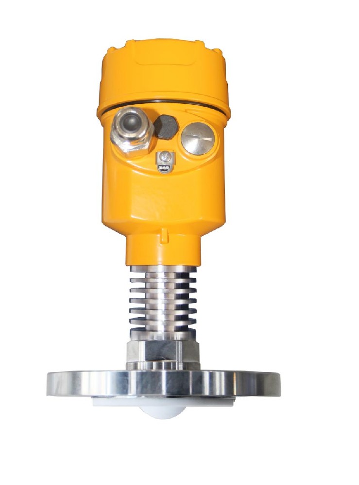
Show the insulation boundary on the installation drawing. Insulating a nozzle can alter where vapour condenses, while covering a cooling section can increase electronics temperature. Review the antenna, connection and enclosure temperatures separately rather than proposing blanket insulation as a cure.
Correct Retention Before Adding a Purge System
Check whether the approved antenna position avoids a condensate trap. Any change to projection or mounting must preserve sealing and the measurement reference. Compare diagnostics through the same heating and cooling cycle afterwards; a dry-room test is not a replacement for that operating check.
Purge is an engineered option only where the offered construction supports it. It introduces gas compatibility, contamination, pressure and monitoring requirements. Do not drill a connection or assume every MV-RD12G includes purge hardware. A supply-header reading also cannot demonstrate flow at a blocked antenna connection.
Condensation Questions
Q1. Does a PTFE antenna guarantee droplets will not matter?
No. Material selection alone does not establish behaviour for every film, deposit or installation. Compare the wet-condition return and the restored dry condition before drawing a conclusion.
Q2. How can cleaning support a diagnosis?
Use an approved method, preserve the as-found evidence and compare the same operating state afterwards. Improvement after cleaning points toward a surface-condition effect, but recurrence still needs investigation of its cause.
Summary
Locate the moisture mechanism before changing thermal arrangements or signal settings. Send the nozzle section, insulation layout and temperature cycle for assessment, with photographs showing the undisturbed condition.
