


 Chinese
 Spanish
 Russian
 Portuguese
 French
 German
 Indonesian
 Thai
 Vietnamese
 Arabic
 Italian
 Turkish
 Polish
 Japanese



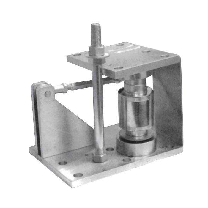
METRAVON MV-WM0025 is a column weigh module with a central sensing assembly, a side restraint connection and a vertical threaded tie rod. Its reference drawing shows a 222.5 mm assembly-height dimension and a 280 mm base length. The protruding threaded hardware needs additional access above the plate. Treat those components as parts of a defined support arrangement, not as proof of a particular lifting or anti-uplift rating.
Check clearance above the column module, not only beneath the vessel
The vertical rod and nut extend above the upper plate in the illustrated assembly. The 222.5 mm drawing dimension therefore is not a promise that every part fits within a 222.5 mm closed cavity. Check the rod projection, nut access and surrounding vessel bracket on the rated outline. Provide the available space in the installed condition and the method for withdrawing or servicing the hardware. A support that can be assembled on a bench may not be serviceable beneath a welded vessel leg.
Define the purpose of the vertical rod before assigning loads to it
The presence of threaded hardware does not supply an allowable uplift force, adjustment torque or safe jacking load. Ask for its intended role, required operating clearances and installation instructions with the selected assembly. Review the side connection separately for its restraint direction and permissible force. Any stability or anchorage assessment must use a documented load path through the vessel, module and foundation; it cannot be based on the appearance of a large rod.
Approve upper and lower fixing patterns independently
The reference plan includes six 18 mm hole references for one interface and nine 18 mm references for the other. These are different patterns, not a requirement to install fifteen foundation anchors. The 280 mm by 200 mm base envelope and the top attachment must be matched to the actual supporting structure. Use the full plan and section to identify fixing positions, contact surfaces and access. The shown 15 mm plate references do not establish the strength of the anchors or of the vessel bracket.
| Item | Value | Selection notes |
|---|---|---|
| Reference drawing height | 222.5 mm | Allow separately for the illustrated rod projection and working access. |
| Reference base length / width | 280 / 200 mm | Check the full top and bottom patterns before drilling. |
| Illustrated plate thickness references | 15 / 15 mm | Not an independent rating for the complete support or foundation. |
| Upper / lower hole references | Six / nine holes, 18 mm diameter | Confirm their assignment from the plan and section; do not combine them into one anchor pattern. |
| Vertical threaded member | Tie rod in the reference assembly | Obtain its intended function, setting and permitted forces. |
| Sensor and assembly rating | Capacity-specific offer required | The mechanical outline does not establish every compatible column sensor. |
Identify a complete rated support instead of a nominal column sensor
The module sheet does not list individual capacity rows. Require the proposed sensor rating together with the mounting drawing and the permitted loads of the assembly. State the vessel tare, operating contents, support positions and other forces that can alter individual reactions. Also request the sensor excitation, calibration output and cable identification for the weighing channel. A higher-capacity sensing element alone cannot demonstrate that the existing seats, retaining parts and support steel are suitable for the new duty.
Record the operating settings during verification
After installation, check the intended seated condition and all restraint settings against the approved instructions. Perform agreed reference loading and unloading with the normal vessel services attached, recording repeat readings and any change associated with movement or contact. Keep the tie-rod setting, side-link condition, rated drawing and calibration together as a maintenance record. If a reading changes after a nut is adjusted, investigate the mechanical cause before re-zeroing. Future spares should be specified from that complete configuration rather than by plate dimensions alone.
Tie-rod function and service clearance
Q1. Is the vertical tie rod automatically an anti-uplift device?
That function needs an assigned allowable force and an approved connection path. The photograph and dimensional drawing alone are not enough. Have the intended role and operating clearance identified in the offered assembly.
Q2. Can the rod be used to lift the vessel for sensor replacement?
Only an explicitly approved lifting arrangement and procedure can establish that use. Do not use the module hardware as an assumed lifting fixture; provide independent temporary support where required by the maintenance plan.
Q3. Will the assembly fit beneath a 222.5 mm vertical clearance?
Not on that dimension alone. The illustrated rod and nut project above the upper plate. Check the full installed envelope, the bracket opening and the space needed for adjustment and removal against the selected rated drawing before approving the installation.
