


 Chinese
 Spanish
 Russian
 Portuguese
 French
 German
 Indonesian
 Thai
 Vietnamese
 Arabic
 Italian
 Turkish
 Polish
 Japanese



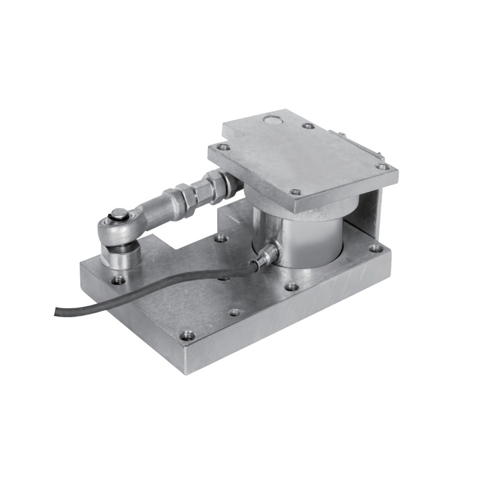
METRAVON MV-WM0024 is a low-profile weigh module with a central compression sensing assembly and an adjustable side link. The reference outline has a 70.4 mm height and a 190 mm base-length reference. Its upper and lower interfaces have different holes and local features. When space beneath a vessel support is restricted, compare the entire assembly envelope and the link-side access before deciding whether the module can replace an existing support.
Assess the low-profile compression module with its side connection
The low vertical envelope does not remove the need for horizontal working space. The link extends beside the central sensor, and its end connection and adjustment must remain accessible after the vessel leg is installed. Mark that orientation on the support plan, together with the cable route and any nearby pipework. A module that fits the available height can still be unsuitable if its side joint cannot be reached or if a fixed obstruction prevents the intended movement.
Separate the top attachment from the base drilling
The upper outline contains three 10 mm hole references and an M8 threaded reference. The lower plan shows six 10 mm holes as well as separate M8 and M12 features. They do not describe one repeated fixing pattern. Use the full outline to assign each hole and thread to its intended component. The 82 mm and 114 +/-0.2 mm references locate different parts of the arrangement; they should not be substituted for one another because the values appear near the same sensor.
| Item | Value | Selection notes |
|---|---|---|
| Reference assembly height | 70.4 mm | Not a rated load or a movement allowance. |
| Reference base length | 190 mm | Check the local base shape, protrusions and cable-side clearance. |
| Upper outline references | 100 / 130 mm | Use the full shape rather than assuming a matching rectangular base pattern. |
| Upper hole / thread references | Three 10 mm holes / M8 | Assign features from the released assembly drawing. |
| Lower hole references | Six 10 mm holes | Separate M8 and M12 features are also shown; they are not extra interchangeable anchors. |
| Upper / lower thickness references | 10 / 20 mm | Obtain confirmation for the offered rated assembly before fabrication. |
Choose a rated configuration rather than assigning capacity from height
No separate capacity schedule is provided with this mechanical outline. Ask for the complete offered rating, its sensor data and any capacity-dependent changes before specifying allowable vessel load. Calculate the highest support reactions from the actual vessel and operating conditions. A 70.4 mm assembly height, a 20 mm base-thickness reference or a familiar cylindrical sensor shape cannot establish the permitted vertical, horizontal or uplift force. Those limits need their own documented configuration.
Release the link setting and the maintenance procedure
The side connection needs a defined installed condition and permissible load. Do not use its threaded adjustment to pull an incorrectly positioned vessel bracket into place. Also agree how the vessel will be supported independently when the sensor or a connection is removed. The module is not a documented lifting point. Include the intended temporary support and access restrictions in the selection review rather than discovering after installation that the sensor is trapped beneath the equipment.
Check the completed support before accepting the weight value
Identify the sensor excitation, calibrated output, resistance and cable functions and match them to the receiving weighing equipment. The outline is not an electrical specification. During commissioning, inspect seating and restraint contact, then compare repeated readings through an agreed reference-loading sequence. Record the link setting and unloading return with the connected services in their normal positions. Give cleaning and corrosion exposure in the enquiry so that the offered sealing and materials can be assessed alongside mechanical fit.
Restricted space and mounting-interface questions
Q1. Does the small height identify the module capacity?
No rating follows from the height alone. Require a matched sensor and assembly specification covering the intended reactions and installation. Do not put a bare-sensor capacity into this outline without that confirmation.
Q2. Can the upper three-hole arrangement be copied to the foundation?
The lower interface has a different pattern and additional features. Release separate vessel-side and foundation details from the complete drawing, with the intended fasteners and structural assessment.
Q3. Can the side link compensate for a misplaced vessel leg?
It should be adjusted only under the approved installation procedure. Using it to force supports into position can introduce loads outside the intended measurement arrangement. Correct the geometry and then verify the installed response.
