


 Chinese
 Spanish
 Russian
 Portuguese
 French
 German
 Indonesian
 Thai
 Vietnamese
 Arabic
 Italian
 Turkish
 Polish
 Japanese



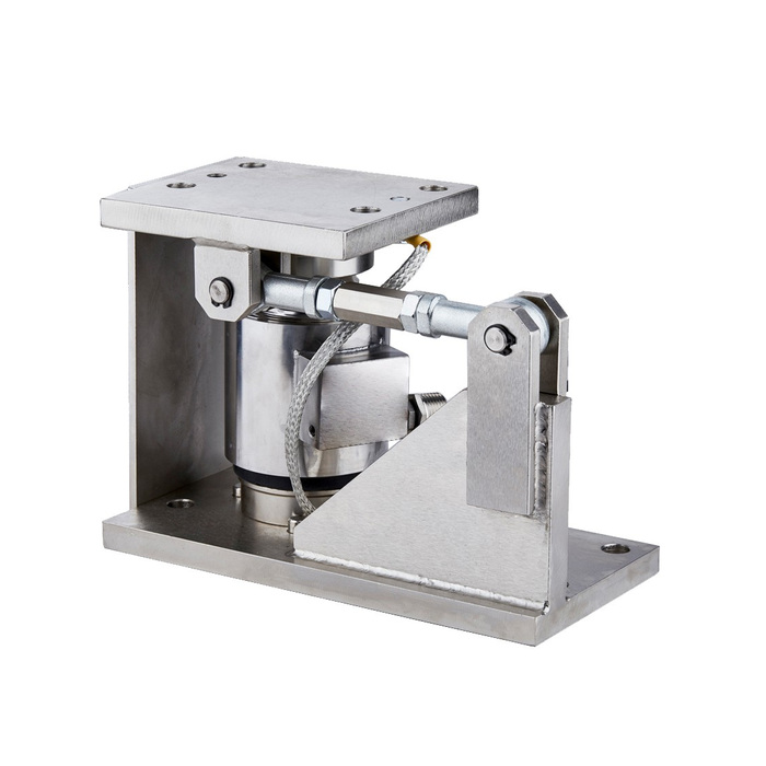
METRAVON MV-WM0018 is a column weigh module with a central sensing assembly and an adjustable side rod between the lower support and upper plate. Its listed ratings are 5, 10, 20, 30 and 50 t. The rod adjustment is part of the mounting arrangement, not an instruction to impose an arbitrary preload. Review vessel movement and horizontal forces before deciding how several such supports should be installed together.
Decide which vessel movements the side rod must control
Mark the direction of each proposed rod on a vessel plan. Consider how expansion, filling, discharge and connected equipment affect the support positions. Opposing adjustments can constrain a vessel differently from the intended design even when each individual module looks correctly assembled. Obtain the permitted rod forces and adjustment procedure for the selected assembly. The adjustable thread does not by itself establish an allowable travel, a tensioning torque or a lateral force capacity.
Use the reference outline for space planning only
The available outline indicates a 265 mm base length, 150 mm upper length and 190.5 mm overall height. These are preliminary envelope references for the illustrated assembly, not a separate approved drawing for every listed rating. Check the rod-side clearance and the space required to reach its joints as well as the base footprint. Obtain the capacity-specific mounting pattern, tolerances, contact surfaces and cable exit before preparing foundations. Leave a practicable route for future sensor removal with the vessel independently supported.
| Item | Value | Selection notes |
|---|---|---|
| Documented ratings | 5, 10, 20, 30, 50 t | Any other rating requires an explicit assembly offer and drawing. |
| Side connection | Adjustable rod | Confirm intended restraint direction, setting and permitted forces. |
| Reference base length | 265 mm | Space-planning value; release the selected capacity drawing before fabrication. |
| Reference upper length | 150 mm | Check the vessel attachment and actual load-transfer position. |
| Reference overall height | 190.5 mm | Do not assume one illustrated envelope proves identical geometry at every rating. |
Distinguish the rated sensor load from restraint and anchorage loads
The nominal tonne rating is not a quantified uplift rating for the side rod or an approval of the supporting steel. Determine vertical reactions and the relevant horizontal or uplift demands separately. Require any claimed restraint capability to be assigned to a specified load path through the module, anchors and vessel structure. Similarly, the column arrangement does not establish a permitted rocking angle or a self-restoring movement allowance without the actual sensor and mounting specification.
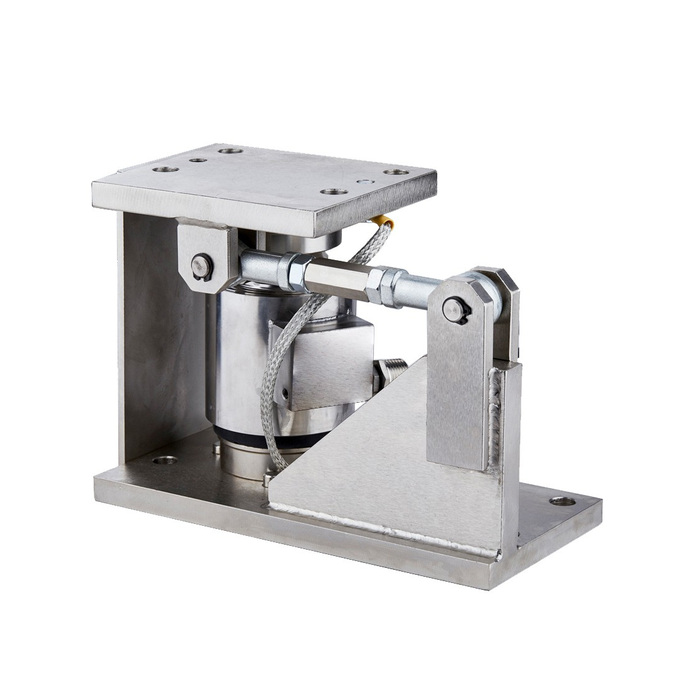
Check the indicated weight when the process moves the vessel
Record whether a change follows a true material transfer, temperature change, pipe movement or restraint contact. Use agreed reference loading under relevant process states to assess the installed measurement. A repeatable empty reading in one condition is not proof of the same response throughout operation. Check rod settings, seating and connected services before applying a new calibration to compensate for an unexplained change. Preserve the approved adjustment record so that maintenance does not unintentionally change the measuring arrangement.
Specify the complete offered configuration
Identify the required rating and obtain its electrical data and calibration with the mechanical offer. The outline provides no universal sensitivity, excitation, bridge resistance or digital protocol. State the receiving instrument, useful weighing interval and environmental exposure so that the sensor and readout can be matched. Request documentary confirmation for material, sealing and any required certification. Ratings outside the five listed values need an explicit offer and rated drawing; do not extend the product range from a similar column sensor.
Rating limits and side-rod adjustments
Q1. Is a 100 t version established by the column construction?
The listed module ratings end at 50 t. A higher-capacity sensor family or similar photograph does not establish a 100 t offer in this assembly. Obtain explicit rating, drawing and performance confirmation for that request.
Q2. Should both rod ends be tightened until movement is impossible?
Use the approved restraint and adjustment procedure. Removing all movement by arbitrary tightening can impose unintended forces. The correct condition must be defined for the actual vessel arrangement and module version.
Q3. Does the column description establish how far the sensor can rock?
No allowable angle or travel follows from the construction name. Check the supplied sensor seats, restraint geometry and permitted movement with the selected rated assembly.
