


 Chinese
 Spanish
 Russian
 Portuguese
 French
 German
 Indonesian
 Thai
 Vietnamese
 Arabic
 Italian
 Turkish
 Polish
 Japanese



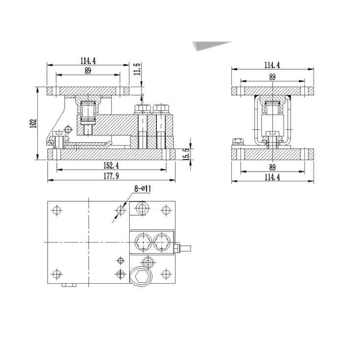
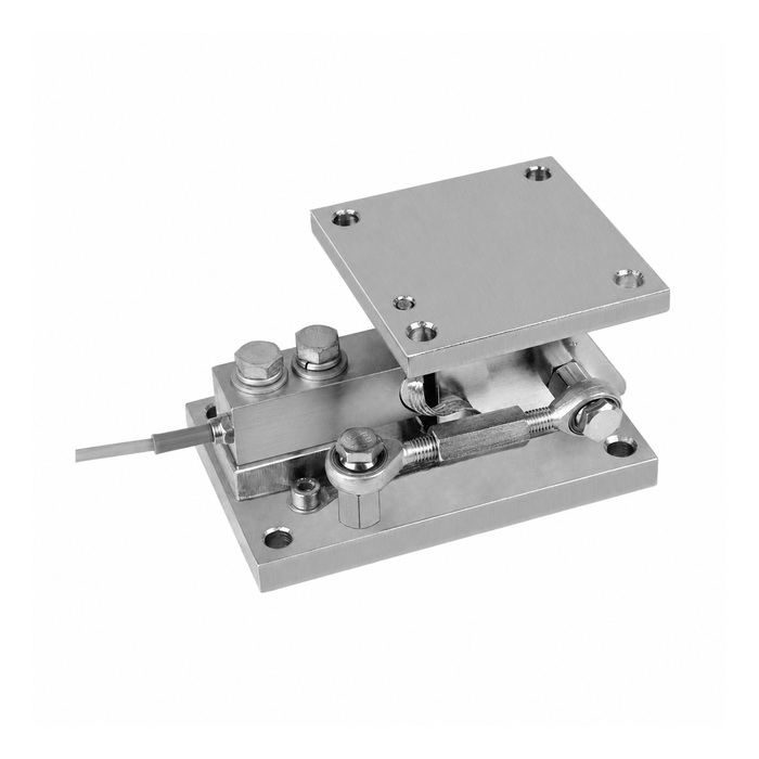
METRAVON MV-WM0021 is a beam weigh module with a square upper plate and a side restraint link visible in the reference assembly. Its two capacity groups use different plate sizes and installed heights: 114.4 mm square above a 102 mm high assembly for 0.25-2.5 t, and 152.4 mm square above a 136 mm high assembly for 3-5 t. Check the lateral access around the link as well as the mounting footprint when planning a vessel support.
Locate the restraint link where it can be adjusted and inspected
A link placed next to a wall or another leg may fit in plan but be inaccessible after installation. Reserve space to inspect its end joints and follow the approved adjustment procedure. Show the rod direction on the vessel support drawing and identify the forces it is expected to resist. The visible turnbuckle-like connection does not establish a permissible lateral force or an arbitrary preload. Do not shorten it simply to pull mislocated supports into place; correct the support geometry first.
Match the upper square and lower rectangular interfaces
The smaller upper plate is 114.4 mm square with an 89 mm fixing reference; the base length is 177.9 mm with a 152.4 mm longitudinal fixing reference. The larger upper plate is 152.4 mm square with a 101.6 mm fixing reference, while the base length becomes 235 mm with a 184.2 mm reference. Keep those two patterns distinct in the installation schedule. A vessel-side plate and a foundation plate perform different attachment tasks even when the module drawing shows both in one view.
Check the rated height and fixing diameter before swapping groups
The increase from 102 mm to 136 mm changes vessel elevation, and the eight-hole reference changes from 11 mm to 17.5 mm. Upper plate thickness increases from 11.5 mm to 17 mm; the lower plate reference rises from 15.5 mm to 24 mm. Do not omit those changes when checking an adapter or replacement. Use the complete rated outline and supporting-structure assessment to confirm that contact surfaces, bolts and access remain suitable.
| Item | Value | Selection notes |
|---|---|---|
| 0.25-2.5 t: base length / width / height | 177.9 / 114.4 / 102 mm | Base longitudinal fixing reference: 152.4 mm; check the full hole layout. |
| 0.25-2.5 t: upper plate / fixing reference | 114.4 / 89 mm | Upper plate is square; upper thickness: 11.5 mm; lower thickness: 15.5 mm. |
| 0.25-2.5 t: hole diameter | 11 mm | Eight-hole reference covers the illustrated upper and lower interfaces. |
| 3-5 t: base length / width / height | 235 / 152.4 / 136 mm | Base longitudinal fixing reference: 184.2 mm; not the smaller group pattern. |
| 3-5 t: upper plate / fixing reference | 152.4 / 101.6 mm | Upper plate is square; upper thickness: 17 mm; lower thickness: 24 mm. |
| 3-5 t: hole diameter | 17.5 mm | Do not replace this value with a rounded 17 mm from another module. |
Separate restraint effects from the weight signal
If a reading changes after link adjustment, inspect the mechanical condition before changing the indicator. A restraint can impose forces that vary with vessel movement, temperature or the state of connected pipes. Record the adjustment and compare readings under agreed reference loads with the final services connected. A zero adjustment alone cannot demonstrate that the error has been removed across the working interval. Include repeat loading and unloading return in the agreed acceptance procedure.
State the sensor and enclosure requirements in the offer
The dimension sheet identifies module geometry but not a common electrical specification. Request sensor sensitivity, resistance, excitation and cable identification with the selected rating. Check the receiving weighing equipment and any junction arrangement against that actual configuration. Give the cleaning and corrosion conditions and require a confirmed material and sealing grade. Neither the side link nor the appearance of the mounting plates establishes a hazardous-area approval, an ingress rating or a complete system accuracy.
The MV-WM0019 cut-out plate arrangement uses different mounting envelopes. Compare both vessel and foundation interfaces before considering it for a support replacement.
Side-link setting and mounting-pattern questions
Q1. Can the side link be used to pull a misaligned vessel leg into position?
That would impose forces not established by the dimensional description. Correct the support geometry and use the approved link adjustment. Obtain permitted loads and attachment details for any intended restraint function.
Q2. Is the 114.4 mm upper square also the lower plate length?
No. In the smaller group the base length is 177.9 mm. Use separate upper and lower interface details; repeating the square pattern at the foundation would misrepresent the module.
Q3. What should be reviewed when changing from the smaller group to 3-5 t?
The height, upper plate, base length, thicknesses and fixing diameters change. Assess the complete vessel support and connected services rather than assuming the original hardware and elevation can remain.
