


 Chinese
 Spanish
 Russian
 Portuguese
 French
 German
 Indonesian
 Thai
 Vietnamese
 Arabic
 Italian
 Turkish
 Polish
 Japanese



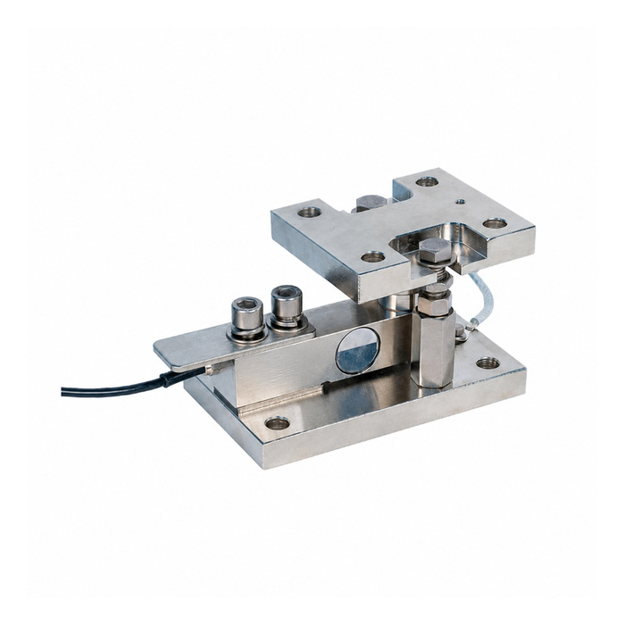
METRAVON MV-WM0019 is a weigh module with a beam-shaped sensor, a cut-out upper plate and a rectangular base. Two mounting envelopes are documented: 0.25-2.5 t and 3-5 t. The larger group changes the base from 210 mm by 100 mm to 270 mm by 150 mm and raises the assembly from 106 mm to 135 mm. Those differences should be reviewed before retaining any existing vessel bracket or foundation.
Check the beam-sensor weigh module envelope against the old support
Measure the full foundation contact, vessel underside and clear height, not only the distance between a convenient pair of bolts. The 29 mm height increase between the two reference groups can affect support levels and connected equipment. An adapter that makes holes coincide may still introduce eccentric loading or insufficient plate contact. Include the proposed adapter and support reactions in the drawing review before steelwork is altered. Do not assume that the lower-range installation has adequate bearing area for a higher load.
Read the eight-hole references with the complete plan view
The smaller outline marks eight 13 mm holes; the larger marks eight 17 mm holes. These are the combined illustrated fixing references, not eight identical anchors to be placed arbitrarily in the foundation. The smaller plan includes longitudinal references of 175 mm and 140 mm and a transverse reference of 70 mm. The larger changes them to 235 mm, 200 mm and 90 mm. Approve the upper and lower patterns separately from the full drawing, including the upper cut-outs and the correct load-contact location.
| Item | Value | Selection notes |
|---|---|---|
| 0.25-2.5 t: length / width / height | 210 / 100 / 106 mm | Upper and lower plate thickness references are each 18 mm. |
| 0.25-2.5 t: hole diameter | 13 mm | Eight-hole outline reference; verify separate upper and lower positions. |
| 0.25-2.5 t: fixing references | 175 / 140 / 70 mm | Longitudinal references: 175 mm and 140 mm; transverse: 70 mm. Use the complete plan. |
| 3-5 t: length / width / height | 270 / 150 / 135 mm | Upper and lower plate thickness references are each 23 mm. |
| 3-5 t: hole diameter | 17 mm | Larger group is not a direct fit into the smaller mounting envelope. |
| 3-5 t: fixing references | 235 / 200 / 90 mm | Longitudinal references: 235 mm and 200 mm; transverse: 90 mm. Release both interfaces. |
Preserve access to the upper connection and retaining parts
The plate cut-outs expose fasteners and surrounding mechanical parts; they are not a reason to select a tightening setting from visual appearance. Request the correct contact condition, retention adjustment and fastener specification for the delivered assembly. Check that the vessel leg does not obstruct that access or touch another part as it moves. The frame and retaining members require their own defined restraint capacities where horizontal or uplift loads are part of the installation.
Include electrical compatibility in a sensor-only spare request
Identify the original sensing element and the proposed replacement calibration, excitation and resistance before retaining the old indicator or junction connection. The module range and plate pattern alone cannot establish signal compatibility. If only the sensor is being changed, include its seating and load-transfer details as well as the electrical schedule. If the whole module is being replaced, verify the vessel elevation and restraints again. Finish with reference loading of the assembled installation and record the result through unloading and repeated applications.
For another beam-module arrangement, compare the MV-WM0021 side-link access and mounting dimensions. Its base sizes, heights and hole diameters differ; a matching capacity interval does not make the assemblies interchangeable.
Retained supports and spare-part identification
Q1. Can the higher group be fitted by enlarging the old fixing holes?
The base length, width, height and fixing positions also change. Compare both structures and the rated reactions. Hole enlargement alone cannot establish adequate support or preserve the vessel level.
Q2. Do eight holes in the outline mean eight foundation anchors?
The drawing represents upper and lower fixing interfaces. Assign holes to the correct plate and use the complete pattern before specifying anchors or vessel-side bolts.
Q3. What is missing from a spare request that only gives the module range?
The sensor calibration and electrical data, contact geometry, mounting group and restraint settings may still be unknown. Include the actual assembly drawing and reader details so that mechanical fit and measurement compatibility can be assessed together.
