


 Chinese
 Spanish
 Russian
 Portuguese
 French
 German
 Indonesian
 Thai
 Vietnamese
 Arabic
 Italian
 Turkish
 Polish
 Japanese



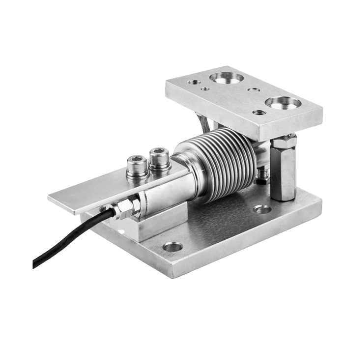
The METRAVON MV-WM0022 bellows weigh module is a compact mounting assembly for small vessels and hoppers. It uses a bellows-covered bending beam between upper and lower plates. Select the assembly against the required support reaction, mounting geometry and operating conditions.
Bellows weigh module capacity and mounting space
The drawing dimensions are a preliminary space check; obtain the rated capacity and load limits for the complete assembly before ordering. Select the individual support rating from the gross load and its distribution. The empty hopper and attached equipment still load the sensor after the display is tared.
| Drawing feature | Dimension | Installation relevance |
|---|---|---|
| Base length | 132 mm | Allow additional clearance for the cable and access to the sensor fixing bolts. |
| Base width | 102 mm | Check the supporting bracket covers the intended mounting area without distorting it. |
| Assembly height | 84.29 mm | Include the module height when checking hopper discharge and connected pipe alignment. |
| Base hole diameter | 11 mm | Use the complete hole pattern and specified fasteners for the final mounting design. |
Prevent small external forces from dominating the result
On a low-capacity hopper, a stiff hose, cable bundle or discharge connection can exert a meaningful force compared with the material being measured. Route those services so that they do not support the hopper or pull it sideways. Check their effect in the installed position, especially if they move during discharge.
Keep the bellows clear of brackets and accumulated material. It protects part of the sensor construction but is not a surface for clamping, supporting the vessel or levering the assembly into alignment. Confirm the selected materials and environmental rating for the intended cleaning process; appearance alone does not establish washdown suitability.
Confirm how the loading contact and retaining parts are intended to work in the supplied installation. Their appearance does not establish an uplift or side-load rating. Where those loads matter, obtain the assembly limits and include them in the support design before approving the module.
Specify the output with the fitted sensor
A mounting kit does not determine whether the complete weighing system communicates digitally. Obtain the selected sensor's output, excitation and calibration specifications, then match a weighing instrument to the required measurement resolution. Any 4-20 mA, RS485 or Modbus RTU connection must be identified on the actual interface device.
For a multi-module hopper, include the sensor count and wiring arrangement when specifying junction boxes and cables. Set the acceptance requirement in the mass units used for the batch; display divisions alone do not establish achievable weighing accuracy.
Small-hopper questions
Q1. Does taring the hopper increase the available batch capacity?
No. The sensor also carries its share of the hopper, fittings and any applied process forces. Calculate the maximum gross reaction at the support; taring cannot create additional mechanical capacity.
Q2. How should a hose connection be checked?
With the hopper safely installed, compare the indicated load before and after the hose is connected in its final position. Repeat the check over the relevant operating movement or temperature range. A repeatable offset at one position can still become a variable error during operation.
Q3. What should I include when ordering several modules?
Specify the capacity of each module, the hopper support layout and whether all sensors must work with one indicator. Identify the cable lengths, junction box, required calibration documents and cleaning exposure. The quotation should distinguish complete modules from loose mounting hardware.
Discuss an MV-WM0022 small-vessel installation with the gross load, minimum batch size, connection layout and available mounting space. Include the permitted weighing error so the sensor and instrument can be assessed together.
