


 Chinese
 Spanish
 Russian
 Portuguese
 French
 German
 Indonesian
 Thai
 Vietnamese
 Arabic
 Italian
 Turkish
 Polish
 Japanese



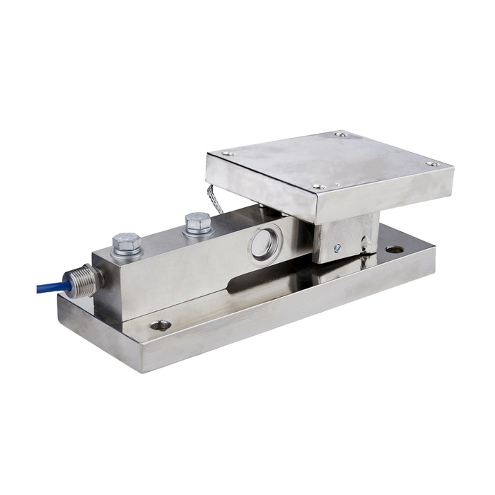
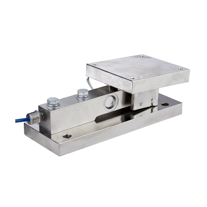
METRAVON MV-WM0016 is a dynamic weigh module with a covered upper assembly and a documented bridge wiring arrangement. Its dimensional reference divides the product into 0.5-3 t, 5-7.5 t and 10 t groups. At 10 t, the H height is 213 mm and G clearance is 3 mm. Those figures must not be replaced with the height or clearance of a similar static or dynamic assembly.
Read the dynamic module G clearance independently of its height
The low and middle groups list G = 1.6 mm; the 10 t group lists G = 3 mm. A G +0.1 reference is indicated at three places in the outline. It is an assembly detail, not a tolerance on the weighing result or an instruction to preload the covered upper member. Obtain the actual adjustment procedure and inspect the relevant contact points during installation. A transport setting, trapped material or an incorrectly adjusted restraint can change the mechanical response even when the displayed zero can be reset.
Confirm the 10 t height before altering connected equipment
The three H references are 103.5 mm, 145 mm and 213 mm. The D base lengths are 286 mm, 318 mm and 360 mm; D1 fixing references are 226 mm, 257 mm and 295 mm. A base length that matches an existing module does not guarantee the same vessel elevation. Check all supporting legs and the effect of any height change on pipes, chutes and restraints. Request the rated drawing before manufacturing an adapter or trying to use software calibration to accommodate unequal support conditions.
| Item | Value | Selection notes |
|---|---|---|
| 0.5-3 t: D / H / G | 286 / 103.5 / 1.6 mm | D1 = 226 mm; D2 = 32 mm; E = M10; F = 13 mm. |
| 0.5-3 t: A / B / C | 150 / 128 / 112 mm | A1 = 124 mm; B1 = 102 mm; C1 = 80 mm. |
| 5-7.5 t: D / H / G | 318 / 145 / 1.6 mm | D1 = 257 mm; D2 = 32 mm; E = M16; F = 17 mm. |
| 5-7.5 t: A / B / C | 178 / 150 / 152 mm | A1 = 146 mm; B1 = 120 mm; C1 = 102 mm. |
| 10 t: D / H / G | 360 / 213 / 3 mm | D1 = 295 mm; D2 = 32 mm; E = M20; F = 21 mm. |
| 10 t: A / B / C | 184 / 152 / 154 mm | A1 = 152 mm; B1 = 122 mm; C1 = 106 mm. |
Wire the bridge by function and confirm the delivered cable
The reference connection identifies red as excitation positive, black as excitation negative, green as signal positive, white as signal negative and yellow as shield. Confirm those functions against the delivered cable schedule before applying power, especially in a replacement involving a previously altered junction box. The diagram establishes a bridge connection, not a specified excitation voltage or calibrated mV/V value. Use the actual sensor data to select a compatible weighing input and follow the system grounding arrangement for the shield.
Specify the moving-load measurement rather than only the display output
Describe the operating cycle, disturbances, largest expected reactions and the time at which the weight value will be used. Have the required sampling and filtering checked with the indicator or acquisition equipment. A smooth display can be too slow for the process, while a fast response may include unwanted mechanical oscillation. No settling time, allowable impact or communication rate is established by the dynamic module name. If the controller requires 4-20 mA or RS485, obtain that interface from a confirmed indicator or transmitter configuration.
Check representative cycles after the restraints are set
Agree on a test sequence that includes repeated cycles, unloading return and the selected reporting interval, using an independent reference where the task allows. Inspect movement and unintended contact as well as the numerical indication. The installation illustrations show rectangular, radial and tangential layouts; select the complete restraint scheme for the actual vessel rather than rotating supports independently. Identify material, sealing and any required certification in the offer, together with the adjustment procedure and electronics needed for the agreed measurement.
For a settled vessel reading, compare the MV-WM0015 static measurement and drawing requirements. Its capacity groups and installed heights differ from this dynamic assembly.
Excitation, height and cycle verification
Q1. Does the bridge diagram permit direct connection to 24 V?
It identifies wire functions, not the permissible excitation. Obtain the fitted sensor electrical specification and use a compatible weighing input. Do not apply a plant supply simply because excitation terminals are shown.
Q2. Can the 10 t unit use the same height as the related static module?
The dynamic reference gives H = 213 mm. Approve the complete rated assembly and vessel elevation; a shared base length is not sufficient evidence of a direct mechanical replacement.
Q3. Does the yellow shield conductor carry the measurement signal?
The diagram identifies it separately from the signal and excitation conductors. Follow the confirmed cable schedule and grounding design; do not use a shield as a substitute for a signal or excitation return.
Q4. What should the acceptance test show beyond a stable display?
It should demonstrate repeatable useful readings at the required point in the operating cycle, unloading return and absence of unintended restraint contact. The reference method and acceptance limits must be agreed for the complete installation.
