


 Chinese
 Spanish
 Russian
 Portuguese
 French
 German
 Indonesian
 Thai
 Vietnamese
 Arabic
 Italian
 Turkish
 Polish
 Japanese


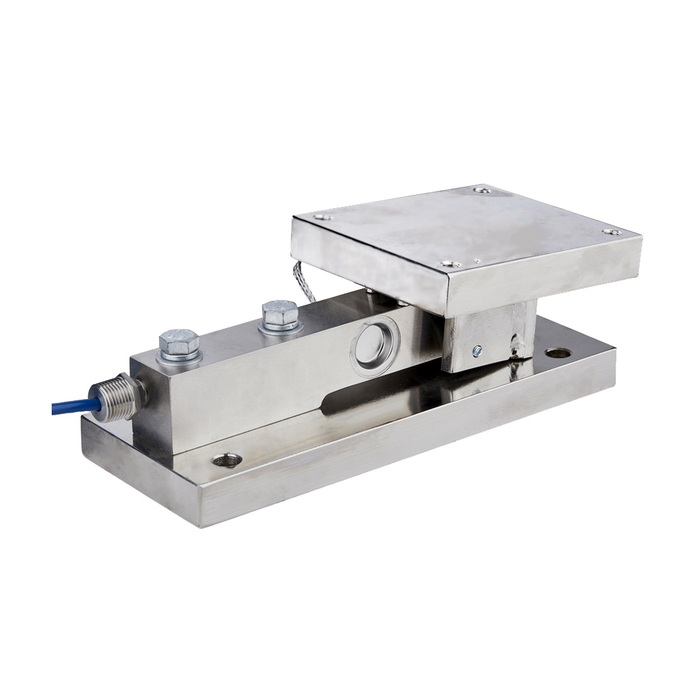

METRAVON MV-WM0015 is a static weigh module for a vessel whose weight is assessed under defined settled conditions. The available static-module dimensional reference lists 2 t, 3-5 t and 10 t groups. A requested 0.5 t, 1 t or 7.5 t assembly needs its own confirmed drawing rather than dimensions borrowed from the related dynamic module. Begin with the intended weighing condition and the vessel support arrangement before selecting a nominal range.
Define when the static weighing value is accepted
State whether the reading is taken after filling stops, after agitation stops or during another repeatable settled condition. Specify the acceptable observation period and useful weight increment. The static designation does not establish a numerical settling time, a total system accuracy or suitability for an arbitrary moving load. A repeatable process condition helps distinguish a genuine contents change from pipe forces, vessel movement or a transient load that is outside the agreed weighing sequence.
Use the static module dimensions, not the covered gallery view
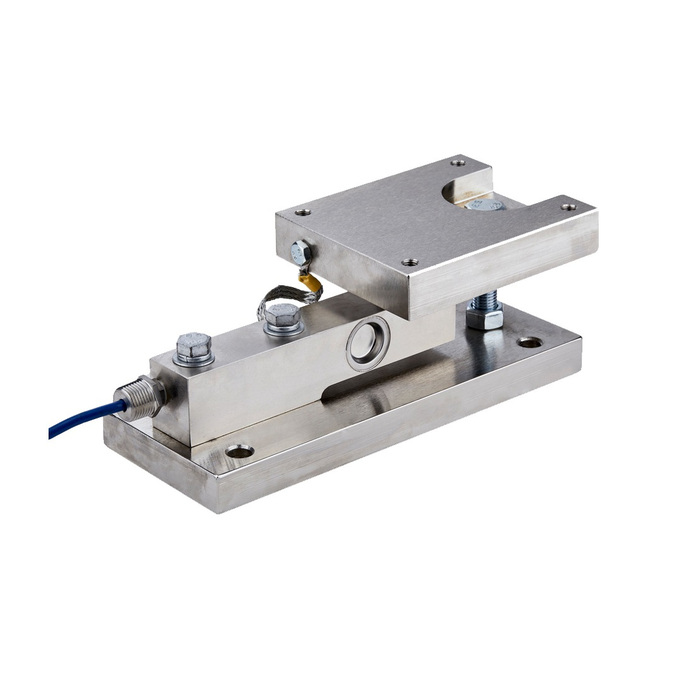
The reference static arrangement has a slotted upper plate and an exposed loading connection. The retained gallery also contains a covered assembly view, so it must not be used to infer this static version or its dimensions. Use the identified static view and the selected rated drawing for that decision. The 3-5 t row specifies L = 317.5 mm and H = 130 mm. At 10 t, L is 360 mm, L2 is 295 mm and H is 168 mm. Similar-looking assemblies elsewhere do not establish these same values.
| Item | Value | Selection notes |
|---|---|---|
| 2 t: L / H | 286 / 102 mm | L2 = 226 mm; upper G = M10; lower P = 13 mm. |
| 2 t: A / B / C | 150 / 128 / 112 mm | A1 = 124 mm; B1 = 102 mm; C1 = 80 mm. |
| 3-5 t: L / H | 317.5 / 130 mm | L2 = 257 mm; upper G = M16; lower P = 17 mm. |
| 3-5 t: A / B / C | 178 / 152 / 152 mm | A1 = 146 mm; B1 = 120 mm; C1 = 102 mm. |
| 10 t: L / H | 360 / 168 mm | L2 = 295 mm; upper G = M20; lower P = 21 mm. |
| 10 t: A / B / C | 184 / 154 / 154 mm | A1 = 152 mm; B1 = 122 mm; C1 = 106 mm. |
Coordinate radial or tangential movement across the vessel
The static reference illustrates radial, tangential and rectangular support layouts. Select an arrangement with the vessel designer, accounting for thermal movement, connected services and required lateral restraint. A pipe or brace can carry part of the vertical reaction even when every module is correctly bolted down. Examine how the whole support arrangement behaves during filling and emptying, not just whether one module can be installed beneath a leg. The illustrated layouts provide no universal allowable expansion or rod-force value.
Identify the sensing element and the environment in the quotation
Have the offered sensor sensitivity, resistance, excitation, calibration and cable functions stated explicitly. The mechanical reference is not an electrical data sheet. Material choice and ingress protection also need a documented offered version; a stainless appearance or an optional-protection category is not a certificate. Describe cleaning, corrosion, temperature and any hazardous-area requirement so that the actual assembly and accompanying documents can be assessed before an order is placed.
Verify tare behaviour with the normal connections fitted
Zeroing an empty tank gives a starting indication but does not prove that its support reactions remain correct at working load. Use agreed reference loads or another independently established verification method through the expected settled operating interval. Record repeat readings and unloading return with pipes, restraints and cables in their final positions. Investigate changes caused by the connected services before altering the calibration. Include the vessel plan, support loads and static measurement sequence in the enquiry so that the proposed assembly can be checked against a defined task.
The MV-WM0016 dynamic-module height and wiring discussion addresses a different operating task and dimensional schedule. Use it to compare requirements, not to extend the static rating table.
Static ratings, gallery identification and connected pipes
Q1. Can a 7.5 t static assembly use the 3-5 t dimensions?
Not without explicit confirmation. The static dimensional reference ends that middle group at 5 t. Request the actual 7.5 t rated drawing and sensor specification instead of extending the interval from a related product.
Q2. Which gallery image identifies the static installation?
The slotted upper-plate view is the static reference used in the detailed section. A covered assembly image is also retained in the gallery and is not dimensional evidence for this configuration. The approved rated drawing remains the ordering authority.
Q3. Is settled weighing possible with connected rigid pipes?
Assess the forces and movement imposed by those pipes throughout operation. A stable unloaded display is not enough; verify the response across working loads and relevant process conditions with the final connections fitted.
