


 Chinese
 Spanish
 Russian
 Portuguese
 French
 German
 Indonesian
 Thai
 Vietnamese
 Arabic
 Italian
 Turkish
 Polish
 Japanese



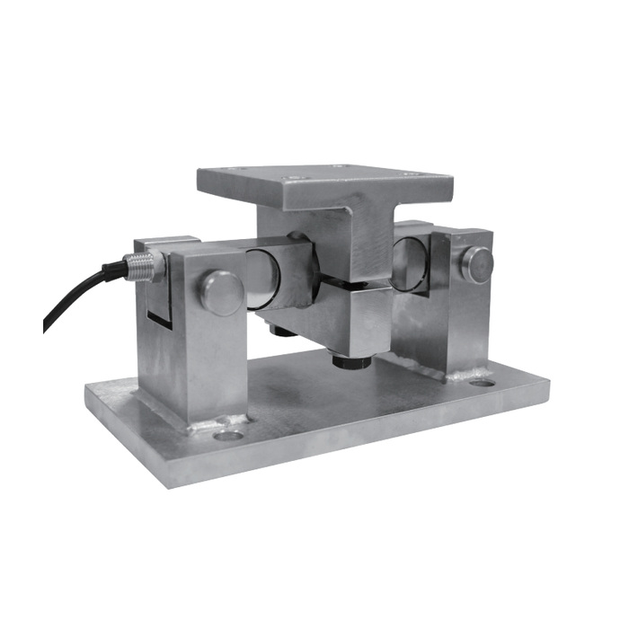
METRAVON MV-WM0014 is a double-shear beam weigh module with two end supports and a central upper loading member. Four mounting-size groups cover listed intervals from 1-5 klb to 100-125 klb. The base length increases from 235 mm to 596.9 mm across those groups. Treat the complete assembly as a structural interface: moving to a higher range can change the vessel bracket, foundation footprint and access needed for replacement.
Choose a mounting size before designing the hopper bracket
The 1-5 klb row has an A base length of 235 mm, B height of 127 mm and C width of 127 mm. At 100-125 klb those references become 596.9 mm, 298.5 mm and 355.6 mm. The intervening groups are not scaled versions that can be approximated from a photograph. Select the required individual rating first, then compare both fixing interfaces and the available surrounding space with the actual row. Do not interpolate a missing capacity into a convenient footprint.
Review beam seats when an existing platform drifts
A loaded platform or hopper can change shape enough to disturb seating or touch a surrounding stop. Inspect the beam end supports, central loading connection and any retained restraints before deciding that the sensing element has failed. Record whether the error appears during loading, persists after unloading or changes when connected equipment is isolated safely. The module has no documented unlimited side-load tolerance; forcing it into misaligned steelwork can defeat the intended vertical force transfer.
Specify anchors and plates from the selected group
I is the fixing-hole diameter reference, increasing from 14.2 mm in the smallest group to 20.6 mm in both middle groups and 28.4 mm in the largest. Shared hole diameters do not establish a shared anchor pattern. D and E change across all four rows, as do the upper plate and fixing references F and G. Compare plate contact areas and the support stiffness as well as bolt locations. Any anchor or foundation design must be checked for the actual reactions and structure rather than inferred from the sensor rating.
| Item | Value | Selection notes |
|---|---|---|
| 1-5 klb: A / B / C | 235 / 127 / 127 mm | D = 158.8 mm; E = 95.3 mm; I = 14.2 mm. |
| 1-5 klb: F / G / H | 101.6 / 69.9 / 12.7 mm | Check plate and fixing locations on the rated outline. |
| 10-35 klb: A / B / C | 304.8 / 200.7 / 203.2 mm | D = 190.5 mm; E = 152.4 mm; I = 20.6 mm. |
| 10-35 klb: F / G / H | 203.2 / 152.4 / 19.1 mm | Hole diameter alone does not establish anchor compatibility. |
| 50-75 klb: A / B / C | 412.8 / 236.2 / 304.8 mm | D = 292.1 mm; E = 241.3 mm; I = 20.6 mm. |
| 50-75 klb: F / G / H | 228.6 / 165.1 / 25.4 mm | Allow for the changed plate geometry and installed height. |
| 100-125 klb: A / B / C | 596.9 / 298.5 / 355.6 mm | D = 508 mm; E = 304.8 mm; I = 28.4 mm. |
| 100-125 klb: F / G / H | 254 / 203.2 / 28.4 mm | Use the larger support outline rather than enlarging an old pattern. |
Retain enough access to remove the beam safely
The assembly photograph shows the sensing beam spanning the two supports beneath a central member. Plan how the vessel or hopper will be supported independently before that beam is unloaded or removed. Include cable access and the space required around the end connections. The retained frame, lifting points and temporary support method need separate approval; the module is not a documented lifting fixture. State maintenance restrictions during enquiry so that the mounting solution is assessed in its installed position, not only on a drawing.
Agree on the delivered measurement configuration
Ask for the exact beam rating, calibrated sensitivity, electrical resistance, excitation and cable identification with the assembly quote. Those values are not supplied by the dimensional table. Give the maximum support reaction and the smallest useful weighing change so that the reader and any signal conditioner can be checked together. Verify the final installation through repeated reference loading and unloading, with the normal connections and restraints in place. Keep the mechanical drawing and calibration settings with the spare-part record to avoid replacing by appearance later.
Foundation reuse and maintenance decisions
Q1. Do the 10-35 klb and 50-75 klb groups use the same foundation?
Their I hole diameters match, but the plate dimensions and D/E fixing references differ. Compare the full foundation arrangement and structural reactions before retaining any existing anchors.
Q2. Should a drifting reading be corrected by replacing the beam immediately?
First inspect seating, restraint contact, attached services and the electrical connection under a safe diagnostic procedure. Establish whether the error follows the sensor or the installation; a new beam cannot remove an external force path.
Q3. Is the module frame suitable for lifting the hopper during maintenance?
No lifting capacity or procedure is established by this description. Provide an independently approved support and lifting method before removing a loaded component. Do not use the sensing assembly as an assumed jacking point.
