


 Chinese
 Spanish
 Russian
 Portuguese
 French
 German
 Indonesian
 Thai
 Vietnamese
 Arabic
 Italian
 Turkish
 Polish
 Japanese



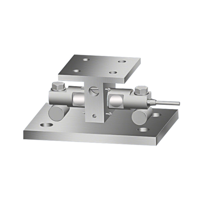
METRAVON MV-WM0013 is a double-shear beam weigh module with a central upper load connection and cylindrical supporting members at the beam ends. Three dimensional groups extend from 5-20 klb to 100 klb. Its upper and lower mounting holes have different diameters. When adapting an existing vessel leg, prepare two interface drawings rather than treating the upper plate as a duplicate of the foundation fixing pattern.
Check upper fixings before specifying foundation hardware
The upper holes are identified by J, while K identifies the lower fixing holes. J is 14.2 mm in the smallest group, 17.3 mm in the middle group and 20.6 mm at 100 klb. K is larger: 26.9 mm, 30.2 mm and 35.1 mm respectively. These are diameter references, not thread specifications or automatically approved bolt sizes. Check the full hole positions, supporting surfaces and required engagement with the selected module drawing before ordering anchors or drilling an upper bracket.
Compare installed height and plate thickness together
B is the overall height reference: 134.9 mm for 5-20 klb, 214.1 mm for 30-75 klb and 263.4 mm for 100 klb. The upper H and lower I thickness references also change. Thin packing under only one support is not a substitute for reviewing all support elevations, foundation flatness and load sharing. Check the clear space needed to access the end connections and remove the sensing assembly. The lowest nominal capacity does not necessarily offer the space or fixing arrangement of another double-shear module.
| Item | Value | Selection notes |
|---|---|---|
| 5-20 klb: A / B / C | 279.4 / 134.9 / 190.5 mm | D = 203.2 mm; E = 101.6 mm; F = 152.4 mm. |
| 5-20 klb: J / K | 14.2 / 26.9 mm | G = 76.2 mm; H = 12.7 mm; I = 19.1 mm. |
| 30-75 klb: A / B / C | 381 / 214.1 / 254 mm | D = 292.1 mm; E = 152.4 mm; F = 203.2 mm. |
| 30-75 klb: J / K | 17.3 / 30.2 mm | G = 130 mm; H = 19.1 mm; I = 25.4 mm. |
| 100 klb: A / B / C | 457.2 / 263.4 / 304.8 mm | D = 355.6 mm; E = 228.6 mm; F = 254 mm. |
| 100 klb: J / K | 20.6 / 35.1 mm | G = 190.5 mm; H = 31.8 mm; I = 31.8 mm. |
Preserve the intended end support and centre loading
Inspect the actual beam seats and central connection during a retrofit. Correct seating, orientation and restraint settings belong in the installation procedure; the visible round supports do not specify permissible travel or a lateral force rating. Submit any guide, stop or vessel restraint that can act on the module. If a support is binding, electronic corner adjustment may reduce one observed discrepancy without correcting the mechanical behaviour through filling and discharge.
Quote the measurement chain with the rated assembly
Specify the requested capacity in klb and the operating display unit separately. Include the useful measurement increment, acquisition equipment and existing junction arrangement. The fitted sensor sensitivity, resistance, excitation and cable schedule must be confirmed before retaining an indicator. The mounting dimensions do not establish accuracy or a process interface. If a transmitter is required, state its supply and receiving input explicitly and have that accessory identified in the quotation rather than assuming it is contained in the beam.
Establish a repeatable support response before final calibration
Use an agreed reference-loading method that exercises the assembled vessel and its normal connections. Compare repeated readings, unloading return and the response when the load distribution changes in a controlled way. Investigate contact, loose seating or connected pipe effects before accepting a calibration adjustment. Retain the approved plate drawings, fixing specification, sensor calibration and reader settings as one replacement record. Those details make a later spare request more reliable than a photograph and nominal capacity alone.
Upper holes, beam supports and retained electronics
Q1. Why are J and K not the same hole size?
They refer to different mounting interfaces. Use J for the indicated upper holes and K for the lower holes, with the complete positions and hardware requirements checked on the rated drawing. A common bolt schedule cannot be assumed.
Q2. Are the cylindrical end supports a specified movement allowance?
The illustration establishes their presence, not a quantified travel or horizontal-load limit. Obtain seating and restraint instructions for the offered assembly and check how the connected vessel is allowed to move.
Q3. What is needed to retain an existing indicator?
Identify the installed input, available excitation, connected sensor count and junction setup. Compare those with the offered sensor calibration, resistance and wiring, then verify the assembled system after the mechanical replacement.
