


 Chinese
 Spanish
 Russian
 Portuguese
 French
 German
 Indonesian
 Thai
 Vietnamese
 Arabic
 Italian
 Turkish
 Polish
 Japanese



METRAVON MV-WM0012 is a double-shear beam weigh module with a central load-transfer connection, an upper mounting plate and a supported lower assembly. The dimensional schedule covers 10-25 klb, 40 klb and 50-75 klb groups. These ratings must remain distinct from metric tonnes. For a vessel support replacement, the main checks are the complete plate arrangement, the available vertical space and the contact geometry around the sensing beam.
Resolve the double-shear beam module drawing references first
The dimensional tables agree on their numerical rows, but the letter positions in the outline revisions are not fully consistent. In particular, the A and B locations differ between the available outlines. The table below therefore retains the tabulated letters as reference values, not an independently released height or foundation schedule. Request one coordinated drawing for the selected rating, with plate length, width, overall height and both fixing patterns explicitly identified. Do not fabricate a vessel stool from a letter-value pair without that check.
Use the complete rated row for an existing support
The 40 klb and 50-75 klb rows both list B = 355.6 mm and C = 292.1 mm, yet A changes from 198 mm to 241.3 mm and E from 203 mm to 286 mm. The rows are not interchangeable merely because two dimensions match. Compare the top plate, bottom plate, force-transfer connection and access around the beam. A capacity increase can require a changed vessel elevation or support bracket; it is not necessarily a sensor-only replacement.
| Item | Value | Selection notes |
|---|---|---|
| 10-25 klb: tabulated A / B / C | 168 / 254 / 190.5 mm | D = 203 mm; E = 203 mm; F = 152 mm. |
| 40 klb: tabulated A / B / C | 198 / 355.6 / 292.1 mm | D = 254 mm; E = 203 mm; F = 190.5 mm. |
| 50-75 klb: tabulated A / B / C | 241.3 / 355.6 / 292.1 mm | D = 254 mm; E = 286 mm; F = 190.5 mm. |
| 10-25 klb: H / J / K | 20 / 152 / 19 mm | Confirm the meaning and location of every letter on one released outline. |
| 40 klb: H / J / K | 28.5 / 152 / 19 mm | Do not infer identical plates from a shared table value. |
| 50-75 klb: H / J / K | 28.5 / 165 / 25.4 mm | The rated drawing must reconcile the differing outline labels. |
Keep the central loading connection free of unintended contact
The illustrated assembly transfers force through the centre of the beam while its ends are supported. The surrounding retaining parts must be set according to the approved installation instructions. They are not evidence of an unlimited horizontal or uplift capacity. Check that the vessel attachment and external restraints do not introduce a competing force path or contact a sensing region. Provide the actual load direction and connected-service forces for review, especially where a retained bracket has been modified or distorted.
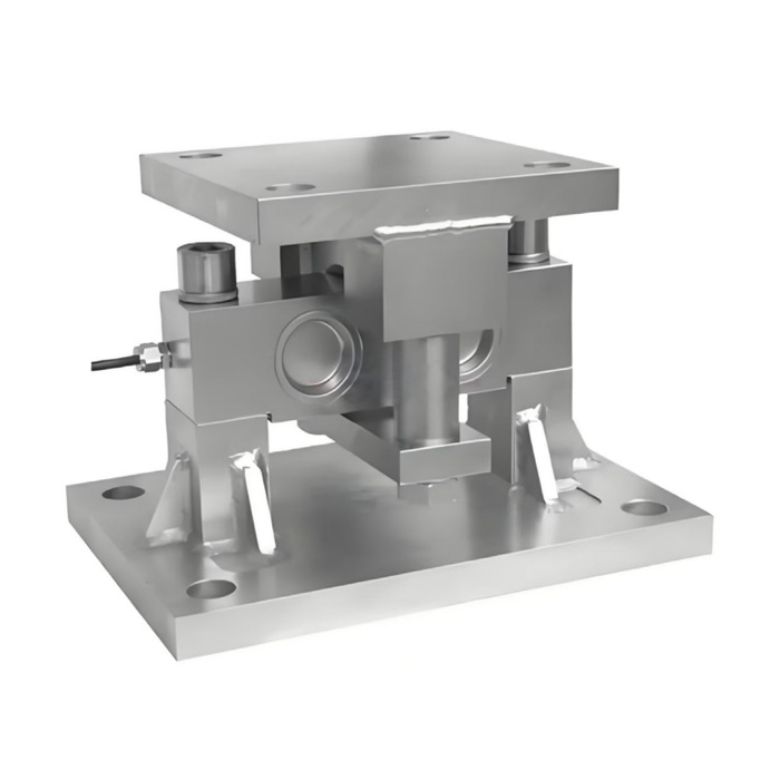
Confirm the signal package instead of borrowing a bare-sensor specification
A mechanical module schedule does not identify every electrical option of the fitted load cell. Ask for its rated output, excitation, input and output resistance, cable functions and calibration value. Then check the selected weighing input or conditioner and the number of connected modules. A request for a PLC current loop or digital connection belongs in the electronics specification; it does not establish that the module itself includes a transmitter or an RS485 interface.
Document the replacement in pounds and the vessel operating unit
The designation klb represents thousands of pounds, not kilograms or metric tonnes. If the plant display uses another unit, identify the conversion and calibration basis explicitly rather than relabelling the nominal capacity. Assess the highest reaction at each vessel support and approve the structure for the relevant operating conditions. At commissioning, record the module rating, released drawing, sensor calibration and repeat readings under agreed loads. Include the return after unloading so that the replacement record describes the completed support, not only a successful zero adjustment.
Drawing release and capacity-unit questions
Q1. Which overall height should be used to design the support?
Have overall height written explicitly on the approved rated drawing. The reference outline revisions differ in letter placement, so a table entry labelled A or B is not sufficient on its own to release steelwork.
Q2. Does a 40 klb module fit wherever a 50 klb unit was installed?
Compare every relevant interface and the force-transfer connection. Several table entries differ even where B and C are shared. Confirm the rated assembly and the vessel elevation rather than relying on the similar photograph.
Q3. Can the indicator be changed from pounds to tonnes without recalibration?
A unit conversion must use the correct basis, and the installed system still needs a verified calibration. Changing a display label cannot establish mechanical suitability, correct sensitivity scaling or the usable vessel capacity.
