


 Chinese
 Spanish
 Russian
 Portuguese
 French
 German
 Indonesian
 Thai
 Vietnamese
 Arabic
 Italian
 Turkish
 Polish
 Japanese



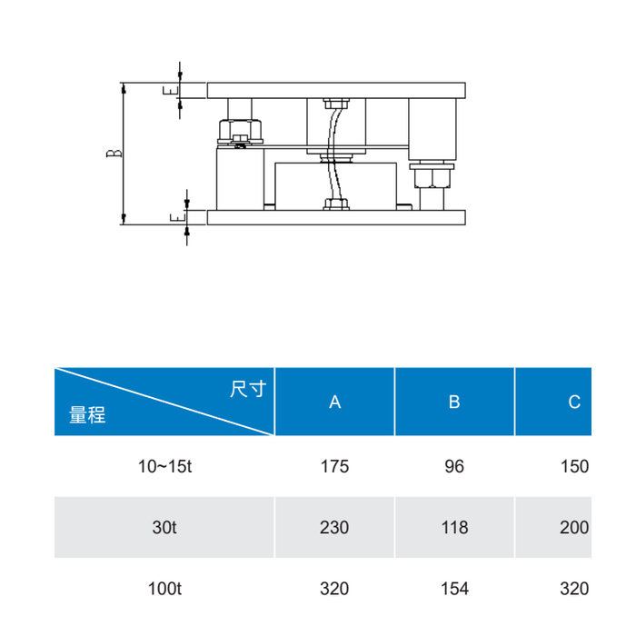
METRAVON MV-WM0010 is a compression weigh module with upper and lower mounting plates around a central load cell. The installation drawing covers a 10-15 t group, a 30 t version and a 100 t version. For a vessel support, check the installed height and anchoring pattern before selecting a capacity: the three groups use different plate sizes.
MV-WM0010 compression weigh module footprint
| Rated load | Plate A x C | Height B | Hole dia. F |
|---|---|---|---|
| 10-15 t | 175 × 150 mm | 96 mm | 14 mm |
| 30 t | 230 × 200 mm | 118 mm | 17 mm |
| 100 t | 320 × 320 mm | 154 mm | 23 mm |
The drawing includes several hole positions, so plate dimensions and hole diameter alone are insufficient for drilling an anchor pattern. Obtain the complete drawing for the selected rating and confirm which holes belong to the vessel connection and which belong to the foundation.
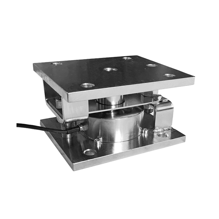
Three checks before the support plates are fabricated
Contact and stiffness. The support must transfer load through the intended bearing surfaces without twisting the module. Specify the plate material, thickness and foundation arrangement through the structural design; the module's rated vertical load is not a rating for an undersized support plate.
Clearance and restraint. Define lateral movement, thermal expansion and any uplift load for the vessel. Confirm the function and setting of the surrounding hardware on the selected assembly. Do not tighten every visible stop against the moving parts simply to make the installation feel rigid.
Service access. Leave a route for the sensor cable and access to inspect contacts, fasteners and debris accumulation. Plan how the vessel will be independently supported during maintenance. The module is a measuring support, not permission to work beneath an unsupported vessel.
From the mechanical assembly to a usable weight signal
Order the load cell specification together with the module: rated output, excitation, wiring, environmental protection and calibration information must identify the actual fitted sensor. The module drawing does not establish a universal mV/V value or a system accuracy.
For a PLC installation, confirm how the weighing instrument will convert the sensor signal and which interface the controller needs. Keep that instrument requirement separate from the mounting kit. A chosen 4-20 mA or communications interface does not resolve mechanical errors caused by pipe forces or unequal support loading.
Commissioning questions
Q1. Does a 30 t module make a four-support vessel a 120 t scale?
Not automatically. The permissible vessel load depends on the most heavily loaded support, the structural design and the operating load cases. Multiplying module capacities ignores unequal reactions, dead load and transient forces. Verify the support calculations before assigning the complete scale a capacity.
Q2. Why might the reading change after the vessel warms up?
Inspect pipe expansion, restraint contact and differences in support movement. Compare the empty or otherwise known-load condition at the relevant temperatures. Re-zeroing at one temperature can hide a mechanical force that will return during the next process cycle.
Q3. How should the acceptance test be recorded?
Document the final support arrangement, selected sensor and instrument settings. Apply known loads using an agreed method, record both increasing and decreasing load, and repeat representative points. Set the acceptance limits from the process requirement rather than inferring them from the module's dimensional drawing.
For an MV-WM0010 quotation, supply the proposed capacity group, vessel support reactions, foundation drawing and required installed height. Include restraint loads and calibration access so that the mechanical and electrical scope can be quoted together.
