


 Chinese
 Spanish
 Russian
 Portuguese
 French
 German
 Indonesian
 Thai
 Vietnamese
 Arabic
 Italian
 Turkish
 Polish
 Japanese



METRAVON MV-WM0009 is a vessel weigh module with a central sensing assembly and a transverse restraint rod. The listed individual ratings are 5, 10, 20, 30 and 50 t. An optional lifting arrangement is also described, but its components and purpose must be identified in the quotation. For vessel maintenance or a new support design, distinguish the vertical weighing function, horizontal restraint and any temporary lifting provision before specifying the package.
Define what the transverse restraint must resist
The rod is a stated structural feature, not a published lateral-force rating. Provide the directions and magnitudes of horizontal forces, vessel movement and the proposed module orientations. Review how several rods interact across the vessel supports so that they restrain the intended movement without creating an unintended vertical force path. Neither the visible rod nor its threaded adjustment establishes an allowable preload. Ask for the approved setting and connection details, including the supporting structure at the rod ends.
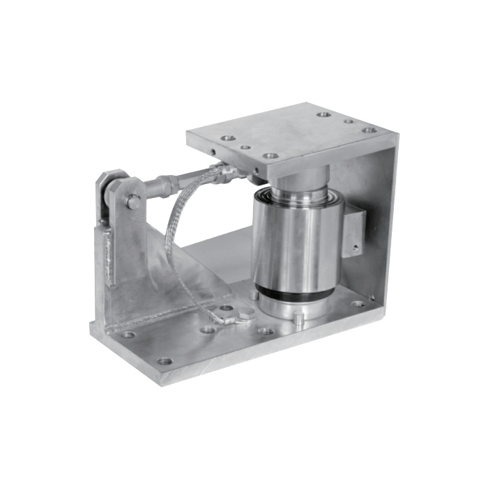
Separate the optional lifting provision from operating restraint
Confirm whether the proposed option is intended for installation, maintenance lifting or another stated function, and obtain its drawing and allowable loads. Do not treat an optional device as included merely because it is mentioned in the product description. A vessel must have an approved temporary support and lifting procedure before a sensing assembly is unloaded or removed. The presence of a rod is not evidence of an anti-uplift rating, nor does it establish a safe jacking point for the full vessel.
Check a rated drawing before reusing a vessel stool
The reference outline shows a 265 mm base length, a 150 mm upper length and an overall height of 190.5 mm. These are useful for an initial space check, but the single illustrated outline is not a complete capacity-by-capacity fabrication schedule for all five ratings. Obtain the selected assembly drawing with the upper and lower fixing patterns, restraint envelope, tolerances and cable exit. Reserve access on the rod side as well as at the sensor; a module can fit beneath a leg yet be impossible to adjust or remove safely.
| Item | Value | Selection notes |
|---|---|---|
| Listed individual ratings | 5, 10, 20, 30, 50 t | Select one rated assembly; the total vessel capacity requires separate assessment. |
| Restraint feature | Transverse rod | Obtain permitted forces, orientation and adjustment instructions. |
| Base length in reference outline | 265 mm | Initial space reference; confirm for the chosen rating. |
| Upper length in reference outline | 150 mm | Check the complete upper attachment and load-contact drawing. |
| Overall reference height | 190.5 mm | Not a released height for every capacity without confirmation. |
| Additional device | Optional lifting arrangement | Specify the actual option, purpose, load limits and scope of supply. |
Package the sensing and readout equipment for the intended measurement
The mechanical description does not define a common sensitivity, supply voltage, resistance or output protocol across the offered ratings. Have the fitted sensor and calibration certificate identified, then match the indicator excitation and input arrangement. Where the plant needs PLC or RTU integration, specify the required measurement value, update behaviour and physical interface for the electronics. An RS485 port must have a confirmed protocol and register definition; the module name alone does not establish Modbus RTU compatibility.
Accept the restrained installation under representative conditions
Calculate the maximum individual reaction from vessel tare, contents and operating forces, allowing for the actual support layout. During commissioning, compare readings across agreed loading and unloading conditions with the final rods and connected services installed. Record adjustments and investigate repeatable changes associated with movement or restraint contact before accepting the measurement. For an enquiry, include the vessel plan, reactions, horizontal loading, space on the rod side, maintenance method and environmental exposure. That information determines whether the complete offered module arrangement can serve the installation.
Restraint, lifting options and maintenance readings
Q1. Does the transverse rod make the module an anti-uplift anchor?
Its stated function is transverse restraint. A separate confirmed uplift capacity and load path would be needed before it could be included in an anti-uplift design. Do not assign that function from the rod appearance.
Q2. Is the optional lifting arrangement included in every quotation?
It must be listed explicitly, with its configuration and intended use. Require the associated load limits and procedure, especially if the option will be used during sensor replacement or vessel maintenance.
Q3. Can the 265 mm outline be used to drill foundations for all five ratings?
Use it only for preliminary space assessment until the selected rated drawing is approved. The single outline does not establish an identical anchor pattern, height or restraint envelope for every offered capacity.
Q4. What should be checked if the reading changes after rod adjustment?
Compare the adjustment with the approved instructions and inspect unintended contact or force transfer. Check connected pipes and vessel movement as well. Re-zeroing alone can hide an offset without resolving an error that changes under load.
