


 Chinese
 Spanish
 Russian
 Portuguese
 French
 German
 Indonesian
 Thai
 Vietnamese
 Arabic
 Italian
 Turkish
 Polish
 Japanese



METRAVON MV-WM0008 is a weigh module built around a central compression sensing assembly between mounting plates. Eight dimensional groups cover listed ratings from 1-4.7 t through a 220 t group. This is not one continuously adjustable 1-220 t module. Plate dimensions, hole diameter and installed height must be selected from the appropriate group, and the final sensor rating must match the largest assessed support reaction.
Equal footprints do not mean equal module heights
The 47 t and 68 t groups share A and B dimensions of 245 mm and 165 mm, but C height changes from 190 mm to 200 mm. The 100 t and 150 t groups likewise share a 260 mm by 180 mm plate reference while their heights are 230 mm and 240 mm. Those differences matter when retaining vessel legs and rigid connections. Do not raise only one support or assume that a higher-capacity assembly can occupy the same vertical space because its anchors appear to align.
Use the compression weigh module size group for foundation design
A and B describe the plate envelope, D and E locate the fixing pattern, and F is the hole-diameter reference. The 220 t row increases the envelope to 360 mm by 280 mm, with D = 290 mm, E = 220 mm and F = 32 mm. The 19 mm plate-thickness callouts in the illustrated outline must not be extended to every high-capacity assembly without a rated drawing. Anchor selection, concrete edge distances, bearing stress and support stiffness require the actual assembly and foundation design, not just the sensor tonnage.
| Item | Value | Selection notes |
|---|---|---|
| 1-4.7 t: A / B / C | 150 / 110 / 115 mm | D = 120 mm; E = 80 mm; F = 11 mm. |
| 10-22 t: A / B / C | 160 / 120 / 130 mm | D = 130 mm; E = 96 mm; F = 13 mm. |
| 33 t: A / B / C | 200 / 140 / 160 mm | D = 160 mm; E = 110 mm; F = 17 mm. |
| 47 t: A / B / C | 245 / 165 / 190 mm | D = 190 mm; E = 120 mm; F = 21 mm. |
| 68 t: A / B / C | 245 / 165 / 200 mm | D = 190 mm; E = 120 mm; F = 21 mm. |
| 100 t: A / B / C | 260 / 180 / 230 mm | D = 200 mm; E = 130 mm; F = 25 mm. |
| 150 t: A / B / C | 260 / 180 / 240 mm | D = 200 mm; E = 130 mm; F = 25 mm. |
| 220 t: A / B / C | 360 / 280 / 330 mm | D = 290 mm; E = 220 mm; F = 32 mm. |
Assess each heavy-vessel support reaction
Start with vessel tare, contents, centre-of-gravity movement and the positions of the supports. Consider filling, discharge, connected pipe forces and external loads relevant to the installation. A high individual module rating does not establish usable contents capacity or eliminate uneven sharing. Include maintenance and installation conditions that may temporarily change the support reactions. The eight dimensional rows identify groups, not every available intermediate rating; request the required nominal capacity explicitly rather than interpolating a missing row.
Specify restraint and service access around the central sensor
The photograph shows threaded restraint hardware beside the central sensing assembly. Its presence is not a quantified uplift or lateral rating, and the adjustment cannot be obtained from a photograph. Obtain the installation procedure, required clearances and confirmed restraint capacities for the offered configuration. Plan a safe means of supporting the vessel independently during sensor maintenance. Room to reach a fastener does not by itself provide enough space to remove the sensor or establish a safe jacking position.
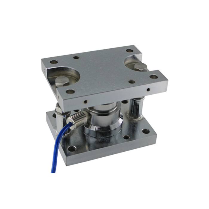
Keep the electrical offer and acceptance method explicit
Require the compression sensor data sheet, calibration value, lead functions and compatible weighing electronics with the mechanical quotation. No universal mV/V value, excitation or IP grade follows from this dimensional table. Specify the useful load resolution and environmental exposure so that the complete system can be assessed. Commission the final supported vessel using agreed reference loads or another documented verification method, checking repeat readings and return after unloading. Record the exact module rating, plate group, restraint setup and indicator scaling for future replacement.
Higher ratings and retained foundations
Q1. Can a 47 t module be exchanged for a 68 t assembly on the same anchors?
Their tabulated fixing references agree, but the 68 t group is 10 mm taller. Check the complete rated drawings, vessel elevation, restraint and sensor electronics before accepting a replacement. Anchor alignment is only part of the assessment.
Q2. Is every capacity between 1 t and 220 t available in one structure?
The reference lists discrete ratings and grouped intervals with different dimensions. It does not establish every intermediate capacity. State the required rating and obtain the corresponding offered assembly rather than using the overall range as an availability list.
Q3. Does the module rating establish the strength of the foundation?
It is not a concrete or anchor design rating. Foundation checks must account for the actual reactions, contact area, anchors, edge distances and supporting structure, together with the approved module drawing.
