


 Chinese
 Spanish
 Russian
 Portuguese
 French
 German
 Indonesian
 Thai
 Vietnamese
 Arabic
 Italian
 Turkish
 Polish
 Japanese



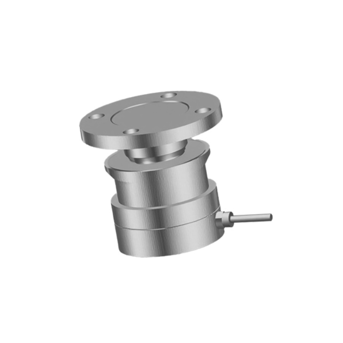
The METRAVON MV-WM0007 compression weigh module uses a round upper flange to introduce vertical load into a cylindrical sensing assembly. It suits a support layout designed around a central compression load path. Flange diameter, mounting height and the reaction at each support determine whether it fits a vessel retrofit.
Compression weigh module dimensions by support group
The smaller assembly and the larger-capacity groups have different interfaces. The following dimensions are for layout screening; the order must identify a specific rated capacity and its matching installation drawing.
| Capacity group | Upper flange diameter | Overall height | Upper hole circle |
|---|---|---|---|
| 1-4.7 t | 90 mm | 81 mm | 75 mm |
| 10-22 t | 100 mm | 95 mm | 80 mm |
| 33 t | 120 mm | 120 mm | 95 mm |
| 47 t | 170 mm | 140 mm | 130 mm |
| 68 t | 170 mm | 150 mm | 130 mm |
| 100 t | 200 mm | 177 mm | 150 mm |
These are dimensional groups, not a statement that every capacity between their endpoints is available. Compare the lower mounting interface as well as the flange: matching the top holes does not establish that an existing foundation or bracket can accept the assembly.
Allow for changes to the vessel support
Adding a module raises the vessel unless the support is redesigned. That change can alter pipe alignment, mixer connections and access around the discharge. Survey the empty vessel's support elevations and the available space before fixing the module height in the mechanical drawing.
The vertical capacity does not specify resistance to uplift, wind or lateral movement. Define those loads separately and identify how the vessel will be restrained without bypassing the weighing path. A flange and mounting bolts should not be assumed to provide a verified anti-uplift system merely because they hold the parts together.
Calculate the highest support reaction using the vessel dead load, contents and load distribution. An off-centre discharge, attached drive or uneven foundation can make one support carry substantially more than the average. The selected module must suit that reaction, including the agreed transient loads.
Specify the sensing and display equipment separately
The mechanical outline does not define the installed cell's output, excitation, bridge resistance or accuracy. Include those items on the quotation together with the load cell identity. Select a compatible weighing indicator and, for a multi-support system, the required junction box and cabling. Do not treat a module mounting kit as a complete PLC interface.
Retrofit questions
Q1. Can I reuse the current vessel flange?
Compare its hole circle, bolt sizes, contact surface and stiffness with the capacity-specific drawing. Also verify that its load acts through the module axis. A matching bolt pattern cannot compensate for an eccentric or flexible support bracket.
Q2. How can pipework affect acceptance results?
A rigid pipe connection can carry part of the vessel load or impose force as temperature changes. Test the completed pipe arrangement, not just a disconnected vessel. Where possible, compare readings before and after connecting each service to identify an unintended load path.
Q3. What should be agreed for calibration access?
Identify where a known load can be applied, how it will be supported and whether the test can cover the operating range. Record loading, unloading and repeated readings at the agreed points. For a large vessel, plan the method before construction makes the necessary access unavailable.
Request an MV-WM0007 support-layout review with the vessel drawing, individual support reactions, existing flange dimensions and required weighing performance. State whether the enquiry covers mounting hardware only or a matched sensor and instrument package.
