


 Chinese
 Spanish
 Russian
 Portuguese
 French
 German
 Indonesian
 Thai
 Vietnamese
 Arabic
 Italian
 Turkish
 Polish
 Japanese



The METRAVON MV-WM0006 is a bellows weigh module for tanks and hoppers, offered in 0.5-2.5 t and 3-5 t capacity groups. Each module supports one point of the vessel. Selection starts with the maximum load at that support, including the empty vessel and attached equipment. Pipe forces and unequal support heights can change the reading even when every sensor is within its rated capacity.
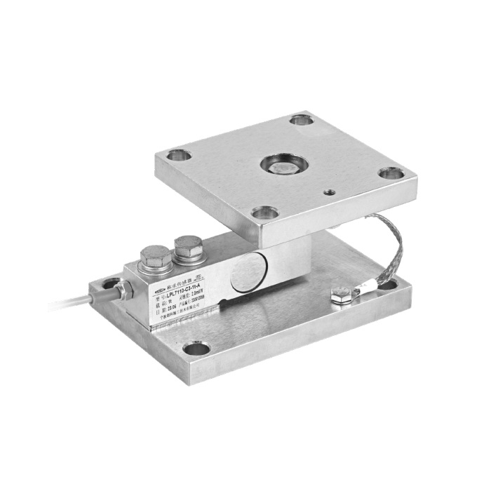
Calculate the service load before selecting a capacity
Add the empty vessel, maximum contents, agitator, insulation, platforms and any permanently attached equipment. Divide by the number of supports, then assess unequal distribution, filling impact, agitation, wind or seismic action and maintenance loads. One support can carry more than the average when the center of gravity is offset or the foundation levels differ.
The module rating applies at each support. Do not use the combined nominal capacity as the only selection rule, and do not assume every support receives an equal share. The vessel structure and foundation must be stiff enough to deliver load consistently to all modules.
Allow for the installed height
The assembly height differs between the two capacity groups. Use these dimensions for initial space planning, then check the full drawing for the chosen capacity before drilling the base or fabricating support brackets.
The height range does not specify how far the vessel may move in service. Restraint clearances and permissible movement come from the assembly drawing. Replacing an existing support also requires a temporary lifting and support arrangement; a taller module can impose load on rigid pipework before any material enters the vessel.
Pipes and restraints can bypass the weighing system
A rigid inlet, outlet or service pipe can pull on the vessel as product temperature changes. The resulting vertical or horizontal force appears as zero shift, poor return to zero or a weight change unrelated to product. Use flexible connections where the process permits, support external pipes independently and arrange them symmetrically when possible.
Ladders, platforms, grounding straps and safety restraints can create the same problem. They must protect the vessel without becoming an uncontrolled parallel load path. For outdoor vessels, the restraint design must also address uplift and overturning; the weigh module should not be treated as the only structural safety device.
Installation sequence for a multi-support vessel
- Survey the foundation elevations and correct soft, twisted or uneven support points.
- Position every module in the designed force direction and keep the upper and lower plates parallel.
- Use temporary supports or jacking points so welding current and erection loads do not pass through the sensors.
- Lower the vessel gradually, then check that every module is seated and able to move as intended.
- Connect pipes and accessories while monitoring zero so external preload is found before calibration.
- Set restraints and stops to their documented clearances after the vessel is in its operating position.
Specify the electrical scope separately
Order the module together with a defined sensor configuration: rated load, sensitivity, excitation, resistance, cable, material and protection rating. A mechanical module designation alone does not establish these electrical characteristics. For multiple supports, the instrument must have enough excitation capacity for all connected bridges.
State whether the scope includes only the modules, a junction box, a weighing indicator, a weight transmitter or a complete PLC interface. If 4-20 mA, RS485 or Modbus RTU is required, identify the instrument that provides it and define the displayed unit, scaling and communication settings.
Choose the weighing indicator after establishing whether the operator needs a local weight display, batch control or a signal for the PLC. The load-cell-to-PLC wiring guide explains where excitation, calibration and scaling belong in that signal path.
Calibrate the installed vessel
Bench data for an individual sensor cannot account for the completed structure, pipes and support balance. Calibrate after mechanical installation using traceable test weights, a substitution method or a documented material test appropriate to the vessel. Apply load in stages and record loading, unloading and return to zero.
Where individual support signals can be observed, compare them before combining the channels. A large imbalance may indicate an uneven foundation, restrained movement or an offset center of gravity. Do not trim a serious mechanical problem out of view at the junction box.
Diagnose weight changes before adjusting zero
Q1. Why does an empty tank change weight when a valve opens?
Pressure or pipe movement may be transmitting force into the tank. Record the indicated weight with the same empty vessel and repeat the valve operation under controlled conditions. Inspect pipe supports and flexible connections. Re-zeroing at one valve position can conceal a repeatable error that returns at the next operating state.
Q2. Why is one module's output much higher than the others?
Unequal weight distribution may be real, but also check foundation level, module seating and a restraint that is carrying load. Compare the outputs using each sensor's calibration data and actual excitation voltage. Equal millivolt readings are not a valid target when sensor capacities or sensitivities differ.
Q3. Can filtering make a mixing vessel suitable for precise batching?
Filtering can reduce display fluctuations, but it adds delay and does not remove the forces from agitation. Define when the batch is weighed, test the settling time and check whether the final cutoff overshoots with the selected filter. If the result is accepted only with mixing stopped, include that condition in the operating procedure.
Request the module and instrument together
Send the vessel support drawing for an MV-WM0006 quotation. Include empty and full weights, support positions, pipe connections, agitation, available installation height and the required weight signal. Identify outdoor exposure or corrosive cleaning conditions. Those details determine the capacity at each support, the mechanical arrangement and the electrical equipment needed to commission the vessel.
