


 Chinese
 Spanish
 Russian
 Portuguese
 French
 German
 Indonesian
 Thai
 Vietnamese
 Arabic
 Italian
 Turkish
 Polish
 Japanese



METRAVON MV-WM0005 is a dynamic weigh module whose mechanical drawing includes capacity-dependent assembly clearances. It is not simply the related standard module with a different cover. The 0.5-3 t, 5 t or 7.5 t, and 10 t groups have different heights and fixing details. For equipment subject to moving or fluctuating loads, the quotation needs the load cycle and required measurement response as well as the largest nominal weight.
Describe the dynamic weighing duty in measurable terms
State what moves, how the load reaches the support, the expected peaks, cycle duration and the time available for a useful reading. A vessel with agitation, a platform receiving a moving load and an installation exposed to occasional impact present different requirements. The dynamic designation alone does not establish a maximum impact force, natural frequency, settling time or permitted throughput. Request confirmation of the mechanical duty and acquisition performance for the proposed assembly before treating it as a solution to vibration or fast weighing.
Preserve the specified assembly clearance
The D entry is 1.6 mm for the 0.5-3 t and 5 t or 7.5 t groups, increasing to 3 mm at 10 t. The outline also marks a D +0.10 reference at three places. These are drawing details, not a general instruction to tighten every retaining part until no gap remains. Obtain the controlled assembly and adjustment procedure for the rated version. Debris, transport restraints or an incorrect setting can introduce another force path; inspection must distinguish intended restraint contact from unintended contact during normal weighing.
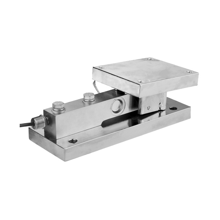
Do not substitute standard-module heights
Although the first two base lengths are 286 mm and 318 mm, their dynamic-module heights are 109 mm and 145 mm. The 10 t assembly is 360 mm long and 177 mm high. Its L2 fixing reference is 295 mm, so using the related standard-module drawing would also misplace that interface. Review the actual space under the equipment and the relative elevations of all supports. Changing one leg height can alter load sharing and connected-service forces even when the other modules remain untouched.
| Item | Value | Selection notes |
|---|---|---|
| 0.5-3 t: L / H / D | 286 / 109 / 1.6 mm | G = M10; P = 13 mm; L2 = 226 mm. |
| 5 t or 7.5 t: L / H / D | 318 / 145 / 1.6 mm | G = M16; P = 17 mm; L2 = 257 mm. |
| 10 t: L / H / D | 360 / 177 / 3 mm | G = M20; P = 21 mm; L2 = 295 mm. |
| Low group: A / B / C | 150 / 128 / 112 mm | A1 = 124 mm; B1 = 102 mm; C1 = 80 mm. |
| Middle group: A / B / C | 178 / 152 / 152 mm | A1 = 146 mm; B1 = 120 mm; C1 = 102 mm. |
| High group: A / B / C | 184 / 154 / 154 mm | A1 = 152 mm; B1 = 122 mm; C1 = 106 mm. |
Coordinate signal filtering with the load cycle
A stable display produced by heavy filtering can conceal peaks or delay the value needed by the controller. Specify which quantity must be recorded: a settled weight, a moving average or another defined measurement. Obtain sensor output, excitation and response details and check the indicator sampling, filtering and communications against that requirement. Neither the module name nor a process-output request establishes a supported sample rate or a Modbus RTU interface. Keep mechanical load limits separate from the settings used to smooth a signal.
Test repeated cycles, not only one stationary load
Agree on a commissioning sequence representative of the actual operating cycle, with an independent reference where practicable. Record repeatability, timing of the usable reading, unloading return and any contact with restraints. Inspect clearances and fasteners using the approved procedure before changing software settings. Include the support drawing, per-module reaction estimates, cycle description and desired reporting interval in the enquiry. Material, protection, cable routing and any junction or transmitter should be identified in the offered package rather than inferred from the photograph.
The MV-WM0004 vessel module dimensions describe a different assembly. Keep its heights and fixing references separate from the dynamic-module drawing when reviewing existing supports.
Dynamic response and adjustment questions
Q1. Does the dynamic designation guarantee accurate weighing during any vibration?
No dynamic error, vibration limit or settling performance is established by that designation. Provide the disturbance and load-cycle details and agree on a representative acceptance test for the selected sensor, module and electronics.
Q2. Can all three groups use the same 1.6 mm D setting?
The 10 t dimensional row lists D as 3 mm, while the lower groups list 1.6 mm. Use the rated assembly instructions and drawing references; do not transfer the lower-group value to a different module.
Q3. Why can two modules with the same base length fail a replacement check?
Installed height, clearances, top interface and fixing positions can still differ. The standard and dynamic 10 t outlines also differ in L2. Check the complete assembly and equipment elevation before approving replacement.
