


 Chinese
 Spanish
 Russian
 Portuguese
 French
 German
 Indonesian
 Thai
 Vietnamese
 Arabic
 Italian
 Turkish
 Polish
 Japanese



METRAVON MV-WM0004 is a vessel weigh module with different upper and lower plate dimensions and three capacity-related mounting groups. Radial, tangential and rectangular arrangements are illustrated for the supports. Choosing between those arrangements affects how the vessel is supported and restrained; it does not change the load rating into a whole-tank capacity. Send a plan view of the supports as well as the required rating when requesting the assembly.
Choose module orientation on the vessel plan
In a radial arrangement, the modules are oriented toward the vessel centre; a tangential arrangement follows the circumference. The rectangular illustration shows another support pattern, not permission to rotate each module independently without checking the system. Establish the intended directions of movement and restraint, including thermal expansion and process forces, with the vessel designer. Mark the cable exits and maintenance access on that plan. A correct individual module footprint does not resolve conflicting restraints between several vessel legs.
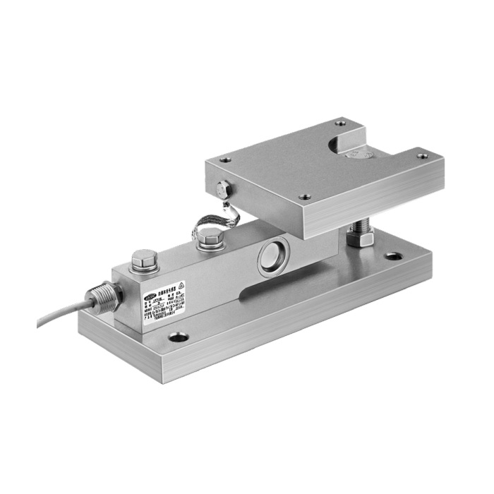
Read upper threads and lower holes as different interfaces
The G references are M10, M16 and M20 for the three dimensional groups. They identify the upper threaded fixing interface. The corresponding P references are 13 mm, 17 mm and 21 mm lower through holes. They are not interchangeable fastener designations. Confirm engagement, fixing positions, bolts, anchors and supporting plate thickness from the approved installation drawing. Do not copy the base anchors into the upper plate schedule or select hardware solely from the module rating.
Compare the complete assembly rather than only its length
Base length L increases from 286 mm at 2 t to 318 mm for 3-7.5 t and 360 mm at 10 t. Installed height H increases from 102 mm to 129 mm and 168 mm. Upper plate dimensions A and B also change, while the base width C differs from the upper width. A retained stool or leg bracket must accommodate the appropriate contact and hole pattern at both elevations. Verify foundation level and structural stiffness before attempting to correct unequal readings electronically.
| Item | Value | Selection notes |
|---|---|---|
| 2 t: L / H | 286 / 102 mm | Upper A = 150 mm; B = 128 mm. Base C = 112 mm. |
| 2 t: G / P | M10 / 13 mm | Upper A1 = 124 mm; B1 = 102 mm. Base L2 = 226 mm; C1 = 80 mm. |
| 3-7.5 t: L / H | 318 / 129 mm | Upper A = 178 mm; B = 152 mm. Base C = 152 mm. |
| 3-7.5 t: G / P | M16 / 17 mm | Upper A1 = 146 mm; B1 = 120 mm. Base L2 = 257 mm; C1 = 102 mm. |
| 10 t: L / H | 360 / 168 mm | Upper A = 184 mm; B = 154 mm. Base C = 154 mm. |
| 10 t: G / P | M20 / 21 mm | Upper A1 = 152 mm; B1 = 122 mm. Base L2 = 292 mm; C1 = 106 mm. |
Specify the sensor package and the system acceptance separately
Obtain a rated sensor data sheet with the module offer, including calibration sensitivity, excitation, resistance and lead identification. The mechanical outline does not establish measurement uncertainty, ingress protection or a standard PLC output. Define the useful weighing increment and expected load interval for the assembled vessel. Agreement on those requirements should precede selection of an indicator, transmitter or junction arrangement. Where several sensors are combined, check their electrical compatibility with that acquisition scheme rather than assuming identical connector appearances establish a match.
Include connected pipework in the commissioning check
Empty-vessel zeroing removes a displayed tare; it does not demonstrate that every support is free to transfer load correctly. With the normal connections fitted, apply agreed loads or another independently verified reference and record loading, unloading and repeated indications. Investigate a reading that changes when a pipe support or restraint is altered. Before ordering, include actual support reactions, vessel movement, fixing drawings, service access and environmental exposure so that the quotation identifies the assembly and accessories needed for that installation.
For a related dynamic arrangement, compare the MV-WM0005 rated clearances and height groups. Similar base lengths do not establish equal height, fixing geometry or dynamic performance.
Orientation, retained bases and pipe connections
Q1. Which is preferable for a circular vessel: radial or tangential mounting?
The selection depends on the intended expansion and restraint arrangement, support positions and external forces. Submit those conditions for an installation plan. The two illustrations do not establish one arrangement as universally more accurate or more stable.
Q2. Can an existing 286 mm base be retained for a higher capacity?
The higher groups use longer bases, different heights and changed fixing references. Check the exact rated assembly against both supporting structures. A similar upper plate or a spare anchor hole does not establish that the old base is suitable.
Q3. Will an indicator adjustment correct a rigid pipe connection?
A calibration adjustment cannot generally remove a force that varies with vessel movement, temperature or process conditions. Address the mechanical connection and then verify the weighing response with the final pipework in place.
