


 Chinese
 Spanish
 Russian
 Portuguese
 French
 German
 Indonesian
 Thai
 Vietnamese
 Arabic
 Italian
 Turkish
 Polish
 Japanese



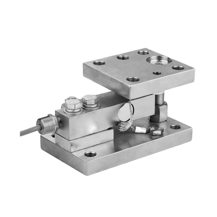
METRAVON MV-WM0003 is a vessel weigh module with a beam-shaped sensing element between upper and lower mounting plates. Its dimensional reference separates 0.25-2.5 t modules from the larger 3 t and 5 t assemblies. Installed height, plate length, fixing holes and load-contact geometry change between those groups. For a tank or hopper retrofit, compare both mounting interfaces before deciding whether the existing support can be retained.
Match the vessel weigh module to the available height
The smaller group has an A height of 99 mm and a B base length of 170 mm. The 3 t and 5 t group increases those dimensions to 129.8 mm and 220 mm. A replacement can therefore fit neither the old elevation nor its foundation even when the load rating appears suitable. Measure the underside of the vessel support, the foundation surface and the space required to remove the sensor. Release the module drawing before fabricating packers or altering connected pipework; the assembly height is not an adjustable mounting allowance.
Check the upper plate independently of the base
For the 0.25-2.5 t group, C is 100 mm and L is 104 mm; the larger group changes these to 120 mm and 135 mm. The fixing references F and D increase from 136 mm and 70 mm to 175 mm and 84 mm. G identifies the hole diameter, not a bolt thread or an anchor specification. Both plates must seat on the intended supporting surfaces, with the load entering through the designed contact. Enlarging old holes does not establish adequate edge distances, plate stiffness or an acceptable load path.
| Item | Value | Selection notes |
|---|---|---|
| 0.25-2.5 t: A / B / C | 99 / 170 / 100 mm | L = 104 mm; E = 17 mm; use the complete rated drawing. |
| 0.25-2.5 t: F / D / G | 136 / 70 / 13.5 mm | H = 15 mm; J = 19 mm. G is a hole-diameter reference. |
| 3 t or 5 t: A / B / C | 129.8 / 220 / 120 mm | L = 135 mm; E = 25.5 mm; installed height changes. |
| 3 t or 5 t: F / D / G | 175 / 84 / 14 mm | H = 18 mm; J = 23 mm. Check upper and lower fixing interfaces. |
Plan the stay rods around the complete vessel
The layout illustrations show stay rods associated with circular and rectangular support arrangements. They do not specify a universal rod count, lateral capacity or tightening setting for every vessel. Provide support positions, vessel movement, connected services and horizontal operating forces for the restraint design. A rod or pipe that unintentionally carries vertical load can affect weighing even if the sensor itself is correctly sized. Distinguish the intended lateral restraint from any additional anchorage required to resist wind, uplift or a process upset.
Order an electrical specification with the mechanical assembly
The module outline establishes dimensions and capacity groups, not a complete electrical performance schedule. Ask for the fitted sensor identification, rated sensitivity, excitation, bridge resistance, cable functions and calibration document. A photograph of a cable connector cannot establish a process output or its supply voltage. If a PLC needs 4-20 mA or an RS485 connection, specify the indicator or transmitter separately and confirm its actual interface; Modbus RTU support is not implied by the mechanical module designation.
Verify weighing with the vessel connections completed
Assess tare and the highest reaction at each support, including unequal loading and external forces, rather than dividing only the contents weight by the support count. During commissioning, compare repeated readings at agreed reference loads and check the return after unloading. Repeat relevant checks with the normal pipes and restraints connected. Record any change caused by those connections before adjusting the indicator. State the required material, cleaning exposure, temperature and sealing grade in the quotation; none follows solely from the plated appearance.
Capacity notation and vessel restraint questions
Q1. Are 3 t and 5 t separate ratings or a 3.5 t module?
They are two listed ratings in the larger dimensional group. The notation does not mean 3.5 t. State the required individual module rating explicitly so that the drawing and sensor calibration identify the same assembly.
Q2. Can the assembly be installed without the stay rods shown in the layout?
That requires an assessment of vessel stability and horizontal restraint. The layout is not an instruction to omit restraint where it is inconvenient, nor does it establish that every application needs the same rods. Approve the complete support scheme before installation.
Q3. Does a stainless-looking photograph establish suitability for washdown?
No material or sealing grade can be established reliably from appearance. Give the cleaning method and exposure conditions and require the offered material, sensor sealing and cable-entry arrangement to be identified in the order.
