


 Chinese
 Spanish
 Russian
 Portuguese
 French
 German
 Indonesian
 Thai
 Vietnamese
 Arabic
 Italian
 Turkish
 Polish
 Japanese



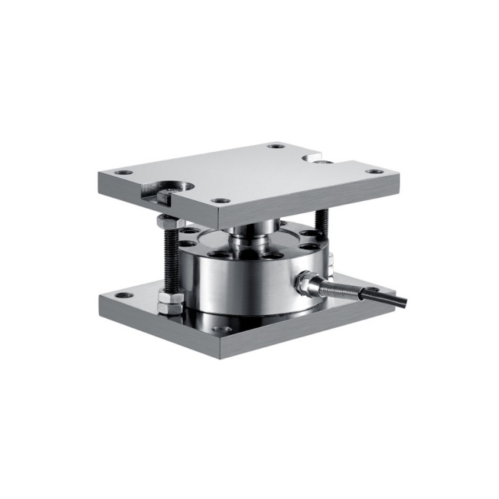
METRAVON MV-WM0002 is a spoke-type weigh module with upper and lower plates and a nominal range of 200 kg-100 t per module. Plate dimensions, installed height and fixing references change across five groups. The electrical table also lists alternative bridge resistances. When replacing a vessel support, specify the complete rated assembly rather than assuming that one familiar plate shape establishes the mechanical fit, restraint function or indicator compatibility.
Compare the spoke-type weigh module plate group with the existing support
The smallest 200-700 kg group is 130/100/80 mm in L/W/H, while the 1-5 t group is 160/115/100 mm. Larger groups reach 200/160/145 mm at 10-20 t, 240/180/175 mm at 30-50 t and 300/240/200 mm at 60-100 t. Use the actual row for the offered rating and confirm both mounting interfaces. Do not scale the old footprint or assume an unlisted intermediate rating shares a neighbouring outline. Keep room for access, cable routing and safe removal of the sensing assembly.
| Item | Value | Selection notes |
|---|---|---|
| 200-700 kg: L / W / H | 130 / 100 / 80 mm | L1 = 110 mm; W1 = 80 mm. Two sets of four 9 mm hole references. |
| 1-5 t: L / W / H | 160 / 115 / 100 mm | L1 = 135 mm; W1 = 90 mm. Two sets of four 11 mm hole references. |
| 10-20 t: L / W / H | 200 / 160 / 145 mm | L1 = 160 mm; W1 = 125 mm. Two sets of four 13 mm hole references. |
| 30-50 t: L / W / H | 240 / 180 / 175 mm | L1 = 200 mm; W1 = 135 mm. Two sets of four 17 mm hole references. |
| 60-100 t: L / W / H | 300 / 240 / 200 mm | L1 = 260 mm; W1 = 200 mm. Two sets of four 17 mm hole references. |
| Input / output resistance alternatives | 750 or 1450 / 700 or 1400 ohms | Confirm the supplied pairing and tolerances before combining modules. |
Release the restraint and seating details with the plate drawing
The illustrated assembly has a central loading contact and surrounding threaded restraint parts. Confirm the intended load direction, seated condition and installation settings from the approved assembly instructions. The self-centring and anti-overturn descriptions do not quantify lateral capacity, uplift resistance or permissible travel. External anchorage, supporting steel and vessel stability need their own assessment. A retained base is acceptable only after checking its contact, fixing and support conditions, not simply because the new module bolts can pass through its holes.
Identify the resistance version before grouping sensors
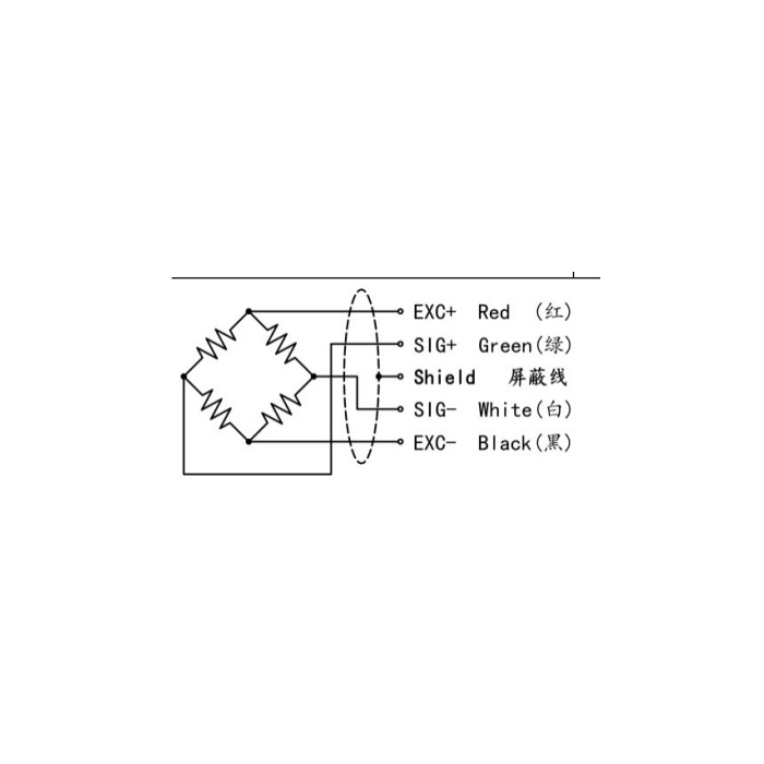
Sensitivity is listed as 2.0 +/-0.05 mV/V at 5-12 V excitation. Input resistance alternatives are 750 +/-30 or 1450 +/-30 ohms; output alternatives are 700 +/-5 or 1400 +/-5 ohms. Obtain the actual matched input/output configuration and calibration details for the supplied version. Do not assume those alternatives can be mixed indiscriminately in an existing parallel connection. Check indicator excitation loading, junction and trimming arrangements, cable functions and the final multi-module calibration before retaining the old electronics.
Choose capacity from the support loads, not only the process label
For a tank, hopper or platform, document tare, contents, support positions and the largest operating reaction at each module. Include external forces that affect the support load and the required freedom of the structure to move. The individual 100 t upper range is not a declaration of allowable vessel contents or of the strength of anchors and pipe connections. Define the useful weighing increment as well as the largest load so that the indicator and selected sensor rating can be evaluated together.
Check the completed installation and the offered protection grade
The non-linearity entry spans +/-0.05 to +/-0.1% FS, while repeatability is separately +/-0.03% FS. Confirm the applicable non-linearity for the supplied rating rather than advertising only the lower endpoint. The reference lists IP65/IP66 alternatives, alloy steel or stainless steel and -20 to +70 deg C operation. Identify the actual material and sealing version for cleaning and corrosion exposure. Accept the installation using agreed loads, repeat readings and zero return with the vessel connections completed. The 150% FS safe-overload entry is not a verified uplift or proof-load rating for the mounting assembly.
The MV-WM0001 cantilever support discussion covers a different load-transfer and plate arrangement. Compare each rated assembly with the vessel support instead of transferring one module mounting pattern to the other.
Mixed bridges, vessel capacity and anchorage
Q1. Can an old junction box be retained because both sensors say 2.0 mV/V?
Compare the actual bridge resistance, calibration, excitation, wiring and trimming arrangement. The sensitivity label alone does not establish that replacement modules will combine correctly with existing channels.
Q2. Does the 100 t maximum describe the tank contents capacity?
It is an individual module range reference. Determine vessel tare and maximum per-support reactions, then assess the whole structure and connected services before setting a usable contents limit.
Q3. Can the anti-overturn feature replace a vessel anchorage assessment?
No quantified uplift or lateral rating is established by that description. Require the approved restraint arrangement and separate assessment of anchors, support steel and vessel stability.
