


 Chinese
 Spanish
 Russian
 Portuguese
 French
 German
 Indonesian
 Thai
 Vietnamese
 Arabic
 Italian
 Turkish
 Polish
 Japanese


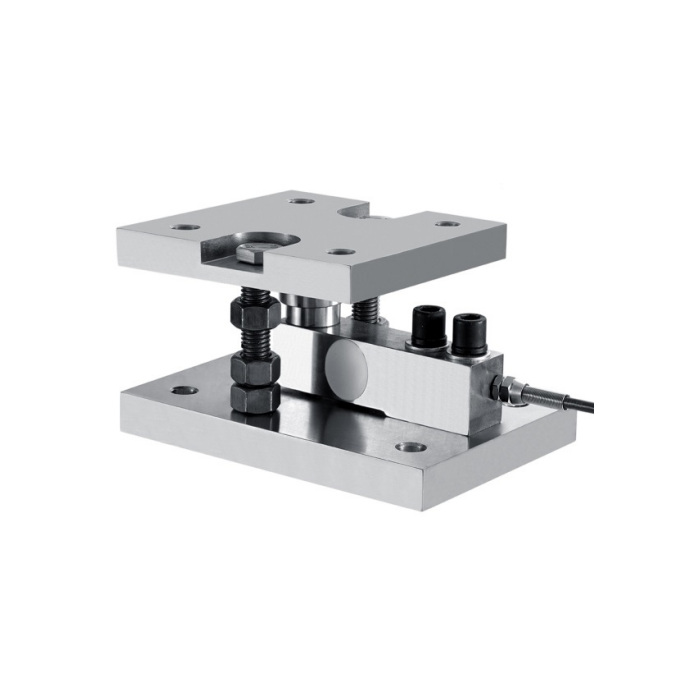

METRAVON MV-WM0001 is a cantilever weigh module combining a sensing beam with upper and lower mounting plates and a defined load-transfer arrangement. The nominal module range is 300 kg-10 t. It is selected for a tank, hopper or platform support, not by treating that range as the capacity of the whole vessel. The complete installation must account for unequal reactions, plate support, connected pipework and the path by which load reaches the sensing beam.
Determine each cantilever weigh module reaction before choosing capacity
List vessel tare, maximum contents, support positions and any equipment carried by the vessel. Assess the largest reaction at each support, including relevant filling, agitation or external-force conditions. Equal division of total weight is only justified when the structural arrangement and loads support it. Include pipework, flexible connections and other attachments that can introduce forces or bypass the measured supports. Increasing sensor capacity cannot correct a pipe restraint that creates an unstable or changing measurement path.
Fit both plates and the full module height into the support design
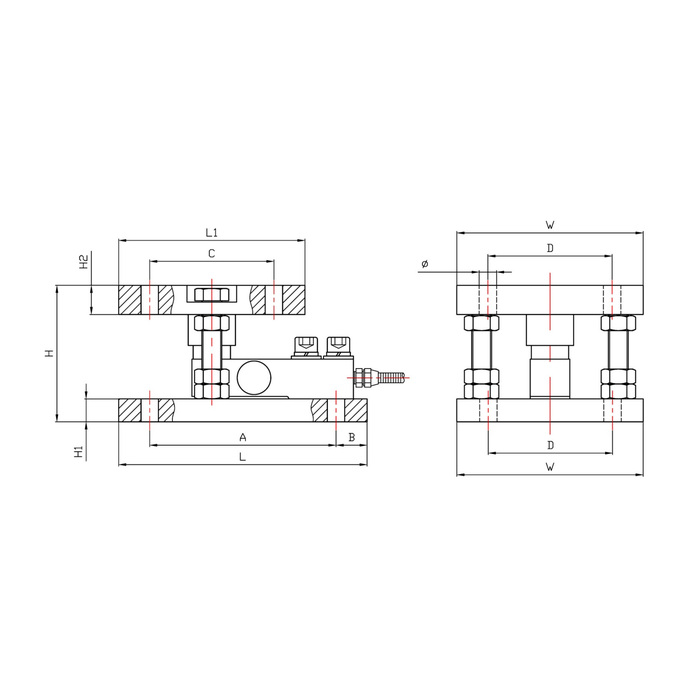
The 300 kg-2 t group lists L/W/H as 200/150/110 mm. The 3-5 t group changes to 232/150/128 mm, and the 6-10 t group to 310/180/174 mm. These are different installed envelopes, not one universal base pattern. The upper and lower plate geometries are not identical in the side view; check the correct interface for each. Obtain the rated hole pattern, plate thicknesses and supporting surfaces before preparing anchors, vessel feet or replacement steelwork.
| Item | Value | Selection notes |
|---|---|---|
| 300 kg-2 t: L / W / H | 200 / 150 / 110 mm | Two sets of four 14 mm holes are referenced; verify both plate layouts. |
| 3-5 t: L / W / H | 232 / 150 / 128 mm | Two sets of four 17 mm holes; do not retain an old pattern by appearance. |
| 6-10 t: L / W / H | 310 / 180 / 174 mm | Two sets of four 27 mm holes; include the larger stack and steelwork. |
| Bridge sensitivity / excitation | 2.0 +/-0.05 mV/V / 5-12 V | Match the selected indicator and actual sensor count. |
| Input / output resistance | 380 +/-30 / 350 +/-5 ohms | Check the junction and excitation arrangement before connection. |
| Module range / whole-vessel duty | 300 kg-10 t / project assessed | Per-support reactions and external forces determine the required rating. |
Keep restraint separate from the normal weighing path
The module description includes self-centring and anti-overturn features, but it does not provide a universal uplift force, side-load capacity or allowable travel. Have the installed restraint and movement clearances approved for the actual vessel and structure. Do not tighten visible retaining hardware into an unintended load bypass to stop movement. Plan safe installation and maintenance support so that the sensor is not used as the sole temporary restraint during lifting, alignment or replacement of a module.
Specify the bridge, junction arrangement and indicator together
The electrical reference is 2.0 +/-0.05 mV/V with 5-12 V excitation, 380 +/-30 ohms input resistance and 350 +/-5 ohms output resistance. For several modules, identify the cable runs, junction arrangement, trimming method and receiving indicator. Confirm excitation loading and the calibration method for the actual number of sensors. Direct 4-20 mA or Modbus RTU output is not established by the mechanical module itself; any PLC or RTU process connection needs the specified weighing electronics and their documented output.
Verify weighing with the vessel connected as it will operate
Complete reference-load and return-to-zero checks with the intended pipework, cable restraints and support hardware in place. Check relevant loading positions and operating states rather than accepting one empty zero. Non-linearity and hysteresis are each listed at +/-0.05% FS, with repeatability and creep separately at +/-0.03% FS. These sensor entries do not guarantee the total tank-weighing accuracy. Specify material and IP66 against actual exposure and the -20 to +70 deg C operating interval. The 150% FS safe-overload entry does not establish a vessel proof load or restraint rating.
For another plated support arrangement, compare the MV-WM0002 spoke-module plate and resistance options. Its footprint, range and bridge alternatives differ; it is not an approved direct substitute for an existing cantilever module.
Vessel capacity, pipe forces and module restraint
Q1. Can four 5 t modules automatically be called a 20 t tank-weighing system?
The vessel tare, unequal reactions, operating forces and structural arrangement must be assessed first. The sum of nominal sensor capacities is not a verified usable contents capacity or a complete system rating.
Q2. Does the module eliminate pipework errors?
It does not remove forces carried by rigid or poorly arranged connections. Review pipe supports, flexible connections and vessel movement with the final installation, then verify the connected weighing response.
Q3. Should all retaining nuts be tightened until the module cannot move?
Use the approved installation instructions and required restraint clearances. Unintended clamping can bypass the sensing path. Visible nuts alone do not establish a torque, preload or movement setting.
Q4. Can it be connected directly to an ordinary PLC analogue input?
The documented signal is a millivolt-per-volt bridge. Provide a suitable weighing input or external indicator/transmitter, with confirmed excitation, scaling and the process interface required by the PLC.
