


 Chinese
 Spanish
 Russian
 Portuguese
 French
 German
 Indonesian
 Thai
 Vietnamese
 Arabic
 Italian
 Turkish
 Polish
 Japanese


Radar level meter replacement is not complete when a parameter file imports successfully. The work may change only an electronic module, or it may move the antenna reference, introduce a different seal and change the output circuit. Define that scope before deciding which earlier checks remain valid.
Radar Level Meter Replacement: Recheck What Actually Changed
| Change | Confirm | Evidence to retain |
|---|---|---|
| Display | Correct supported part and access to the intended variables. | Part identification and restored display settings. |
| Electronics | Hardware, firmware, supply and output compatibility. | Parameter comparison and complete output-chain test. |
| Antenna | Reference plane, mounting geometry and measurement configuration. | New dimensions and echo checks across the useful range. |
| Seal | Material, connection requirements and process conditions. | The specified replacement and required assembly inspection. |
| Whole unit | All mechanical, electrical and application requirements. | Updated asset identity and a new accepted installation baseline. |
This is a scope guide, not authorisation to dismantle every part in the field. Use the manufacturer's permitted service procedure and the site's isolation requirements. If a repair changes an approved assembly or its required certification, resolve that change before returning it to service.
Save the Old Condition Before Removing the Instrument
Where the unit still operates, preserve its parameters, selected output variable, echo information and status at a known process condition. Photograph the mounting and connections. Record the PLC value and an independent reference if available.
If the failed device cannot be read, identify the date and applicability of the last controlled backup. Do not reconstruct undocumented echo suppression or offsets from the nominal range on the nameplate. Mark missing evidence explicitly so the commissioning plan can address it.
Do Not Infer Interchangeability From MV-RD12 and MV-RD13 Housings
The METRAVON MV-RD12 and MV-RD13 have different lens sizes, beam angles and process-connection arrangements. A similar enclosure does not establish a compatible electronics spare or permit an unchanged parameter import between them.
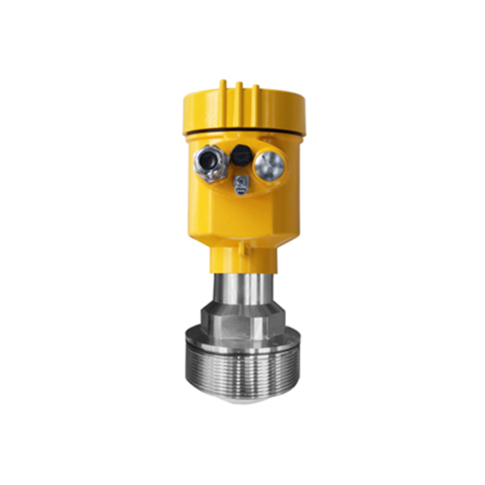
Ask whether the offered part is supported for the installed serial number and configuration. Confirm which settings transfer, which require manual entry and which must be re-established by testing. Keep the original backup unchanged and record intentional differences separately.
Prove the Restored Measurement in Three Stages
- Compare the delivered assembly with the accepted order. Check the connection, reference position, seals and output wiring before applying power or exposing it to the process.
- Verify the detected surface and local distance at suitable reference conditions. Recheck fixed echoes if the antenna, nozzle or surrounding structures changed.
- Verify the receiving values, scaling, invalid-data response and required alarms through the complete system. Remove test modes and temporary overrides before release.
An output simulation can prove a loop without proving the microwave measurement. Conversely, a correct local reading cannot prove that the PLC is using the right scale. Keep these tests separate in the record so neither result is used as a substitute for the other.
Do not reuse a false-echo map just because the old device used it. Establish that its recorded distances still correspond to the same fixed features and that it does not cover the wanted surface. Use the echo-mapping checks where the geometry has changed.
Replacement Questions
Q1. Can a working backup be accepted without comparing individual settings?
No. Import success does not confirm that every field is supported or interpreted identically. Review geometry, output assignment, units, addresses, fault behaviour and any conversion table against the new unit's documentation. Record the as-left values rather than only the file name.
Q2. Must a replacement always be tested during filling?
The required test should cover the conditions that determine performance. Where the original fault or application risk occurs during filling, a stationary check leaves that condition unresolved. Agree on a controlled operational observation and any temporary limitation before release.
Q3. What makes a spare-parts enquiry precise?
Include the installed identification, photographs, firmware where accessible, process connection and output requirement. State whether the aim is a supported module repair or a complete replacement. Those are different supply scopes and should not be quoted as interchangeable options without review.
Summary
Preserve the old evidence, verify the supported replacement and create a new tested baseline. Submit the installed radar identification and replacement scope before ordering. The handover should explain what changed and what was revalidated, not merely state that the display returned.
