


 Chinese
 Spanish
 Russian
 Portuguese
 French
 German
 Indonesian
 Thai
 Vietnamese
 Arabic
 Italian
 Turkish
 Polish
 Japanese


Radar installation in bulk-solids silos should be settled before the roof nozzle is fabricated. The installation has to observe a useful part of a changing pile while keeping the instrument away from direct material impact. A convenient roof opening is not necessarily a useful measuring position.
Mark the Material Routes on the Roof Drawing
Show every inlet and discharge point, including alternative filling routes. Mark roof steelwork, filters, ladders and access platforms on the same drawing. Then trace the likely pile surface during filling and discharge. The surface beneath the radar can move differently from the average inventory.
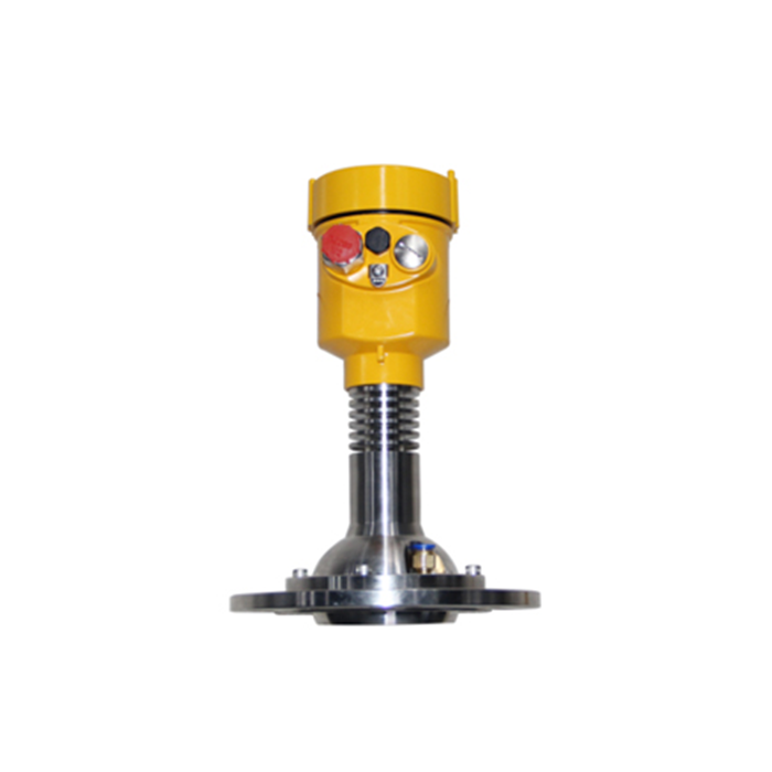
The MV-RD21 has a listed 3-degree beam and 76 mm PTFE lens. Its narrow path can help separate the target from internals, but its footprint still grows with distance. Check it at the lowest required surface as well as near the roof.
Radar Installation in Bulk-Solids Silos: Release Checks
| Stage | Confirm | Hold installation if |
|---|---|---|
| Layout | The intended surface remains visible through the operating cycle. | The mounting point only observes the inlet stream or an unrepresentative region. |
| Nozzle | Antenna clearance, reference position and approved projection. | A reducer or long passage screens the antenna. |
| Support | Roof capacity, rigid mounting and repeatable orientation. | Vibration or servicing can change the aim. |
| Access | Safe inspection of the antenna and cable entries. | Routine deposit removal would require an unplanned unsafe approach. |
Make Protection Compatible With the Beam
Keep direct falling material away from the antenna. A guard must not create an additional reflector in the measurement path or a pocket that collects dust. Review its position after installation, not only the instrument before the guard was fitted.
Combustible dust requires the project's documented hazardous-area assessment and suitable equipment evidence. Do not infer approval from a metal enclosure or a high ingress rating. Similarly, purge fittings are not a standard solution for every deposit; verify the offered construction and the effect of the gas on the process.
Use the First Operating Cycle to Establish the Baseline
Save the empty or low-level curve where safely possible, then observe filling, settling and discharge. Record the selected distance, measurement status and receiver value with the material state. Inspect for impact marks or early deposits at the first safe opportunity.
If the radar is used for inventory, link its position to the volume and density assumptions. Do not change an offset simply to force a wall-side reference to match a reading taken on a central pile.
Silo Installation Questions
Q1. Should the radar always sit halfway between the wall and centre?
No universal fraction accounts for different inlets, outlets and internals. Select a position from the flow pattern and verify the actual observed surface.
Q2. Does a steady reading prove that material is leaving the silo?
No. A bridge can leave a visible upper surface while the outlet stops flowing. Where discharge confirmation matters, use appropriate feeder or flow evidence rather than relying on the level value alone.
Summary
Approve the roof layout, protection and observation point as one installation. Send the roof plan, inlet routes and discharge arrangement for an MV-RD21 mounting review.
