


 Chinese
 Spanish
 Russian
 Portuguese
 French
 German
 Indonesian
 Thai
 Vietnamese
 Arabic
 Italian
 Turkish
 Polish
 Japanese


Weak radar echoes in liquid tanks need a diagnosis before a replacement instrument is selected. A low-reflectivity liquid, foam, antenna deposits and changing gas-space conditions can produce different problems. Recording when the return deteriorates is more useful than describing every unstable reading as a foam problem.
Weak Radar Echoes in Liquid Tanks: Separate the Likely Causes
| Clue | Possible cause | Useful evidence |
|---|---|---|
| Clean, steady liquid | The surface reflection may be weak relative to the bottom or fixed internals. | Liquid identity and properties, distance, reference level and echo diagnostics. |
| During mixing | Foam, a disturbed surface or a moving obstruction may change the selected return. | Mixer state, foam observations and simultaneous level-reference records. |
| After a thermal cycle | Condensation, deposits or changed process conditions may affect the measurement. | Temperature and pressure history, composition and the antenna's as-found condition. |
These clues narrow the investigation but do not identify the cause on their own. A wet antenna does not prove that vapour blocked the signal. Equally, a low dielectric constant does not explain a new fault if the liquid and installation have not changed.
Establish Whether the Instrument Is Following the Surface
Compare the measured distance with an independent, safely obtained level reference. At several available levels, determine whether the selected echo moves with the surface or remains near a fixed distance. Preserve the curves before modifying echo suppression or sensitivity. A stronger reflection from an internal fitting is not necessarily the right target.
Check the local display against the receiving system early. If the instrument is stable but the PLC value changes, investigate wiring, scaling or communications separately; changing the antenna will not correct that data-path fault.
Use Process Changes to Test the Diagnosis
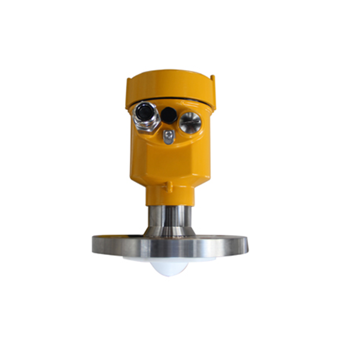
For an MV-RD12 application, the listed liquid range is not a guaranteed range for every low-reflectivity material. Submit the operating liquid, temperature, distance and installation drawing for review. Do not invent a minimum dielectric threshold from the model name.
Where the fault starts during aeration or mixing, correlate it with the actual process state. If foam is implicated, use the separate foam measurement assessment to decide whether liquid height or foam height is required. Do not average readings from two different surfaces into one plausible level.
Where the fault follows cooling, inspect the antenna and nozzle under the site's safe access procedure before wiping away evidence. Compare behaviour before and after an approved cleaning step while accounting for process changes. The condensation review covers mounting and inspection details.
Fault-Report Questions
Q1. Is increasing sensitivity a useful first test?
Not without identifying the competing reflections. It may strengthen detection of an unwanted target as well as the surface. Keep the original configuration and follow the instrument-specific procedure after reviewing the diagnostic evidence.
Q2. What makes a replacement enquiry actionable?
Include the fluid and process cycle, actual low-level distance, nozzle section, internal obstacles, raw distance trend and independently known levels. State whether the fault occurs continuously or only during one operating stage. This helps distinguish a range or reflection limitation from an installation fault.
Summary
Identify the selected target, separate process effects from installation and data-path faults, and change one justified item at a time. Send the diagnostic records with a liquid-radar application enquiry before deciding that a different antenna or measuring principle is necessary.
