


 Chinese
 Spanish
 Russian
 Portuguese
 French
 German
 Indonesian
 Thai
 Vietnamese
 Arabic
 Italian
 Turkish
 Polish
 Japanese


False echoes in radar level measurement are suspected when the instrument follows a return that does not represent the required material surface. A wrong displayed level alone is not proof: an incorrect datum or receiver conversion can create a similar symptom while the radar tracks the correct distance.
Keep the Fault Evidence Before Changing Settings
Record the selected distance, reported level, process activity and diagnostic curve at the same time. Obtain an independent surface reference where it is safe and practical. Save the current parameters before adjusting sensitivity, damping or suppression, otherwise the original cause can become difficult to reproduce.
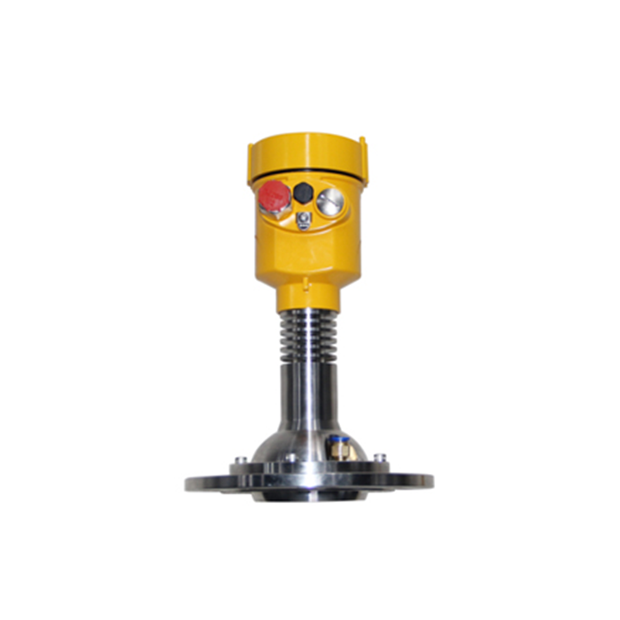
For the METRAVON MV-RD21 solids radar, include filling and discharge state. Its 76 mm PTFE lens and listed 3-degree beam help define the observed region, but the return can still change with the pile and filling stream. Compare the actual observed point, not a reference taken at an unrelated wall location.
False Echoes in Radar Level Measurement: Sort the Evidence
| Pattern | Possible cause | Next check |
|---|---|---|
| Fixed distance | A stationary internal return may have been selected. | Compare its distance with measured nozzle and structure positions while the surface moves. |
| Fill-only jump | The stream, dust or a changing pile can affect the selected return. | Capture the event and compare with the settled condition at similar inventory. |
| Wet-antenna fault | Condensate or coating may alter the near-field response. | Inspect as found and compare diagnostics after approved cleaning. |
| Constant offset | The correct distance may be converted using a wrong datum. | Check the reference plane before declaring an echo-selection fault. |
| PLC-only jump | The measurement may be sound but its transmission or conversion is not. | Compare local distance with raw receiver input and the final tag. |
Change One Cause and Preserve a Comparison
First inspect physical conflicts that the drawing can explain: an antenna recessed in a restrictive nozzle, accumulated material, a new brace or a shifted mount. Correcting an identifiable installation issue is preferable to storing a broad suppression map over the useful measurement region.
When a fixed target remains unavoidable, use the controlled false-echo mapping procedure. Where only the receiver jumps, follow the PLC signal-chain diagnostic instead. These investigations need different evidence.
Repeat the operating condition that produced the fault after each justified change. Keep before-and-after curves with the same distance scale and process description. A quiet display during an idle period does not prove that a fill-only problem has been corrected.
Diagnostic Questions
Q1. Is the strongest peak always the product?
No. Metal internals can produce strong reflections. Correlate position and movement with independent geometry and process information rather than identifying the material by amplitude alone.
Q2. Will higher damping stop wrong-target jumps?
It can slow the displayed change without correcting target selection. Confirm the target first, then check that response filtering still meets the process timing requirement.
Summary
Classify the fault from synchronised evidence before changing echo settings. Send the fault-time curve, selected distance and vessel section for diagnostic review; include a normal-condition comparison if available.
