


 Chinese
 Spanish
 Russian
 Portuguese
 French
 German
 Indonesian
 Thai
 Vietnamese
 Arabic
 Italian
 Turkish
 Polish
 Japanese


A radar level meter beam angle becomes useful when it is drawn against the actual vessel. The antenna centreline may miss a ladder while the wider measurement path intersects it farther down. Check clearance to the lowest required surface, not just the space immediately below the nozzle.
Translate Radar Level Meter Beam Angle Into Clearance
For an initial geometric estimate, the nominal beam diameter is D = 2L tan(theta/2), where L is distance from the antenna and theta is the full beam angle. Use consistent distance units. At a longer measuring distance, the same antenna covers a wider area. This is a planning calculation, not a boundary outside which reflections cannot occur.
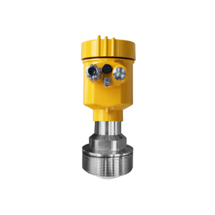
The METRAVON liquid-radar options below illustrate why an order should identify the antenna, not just say 80 GHz. Their listed angles differ with antenna size. Confirm the offered drawing before reserving a process opening.
| Model | Antenna | Drawing review |
|---|---|---|
| MV-RD11S | 21 mm PTFE; listed beam angle 14 degrees. | Check the wider footprint in a compact tank and clearance to its wall. |
| MV-RD12 | 32 mm PTFE; listed beam angle 8 degrees. | Locate the beam relative to inlets, braces and the usable low level. |
| MV-RD13 | 76 mm PTFE; listed beam angle 3 degrees. | Check the larger antenna connection and whether the narrow path sees a representative surface. |
A Small Angle Does Not Approve a Nozzle
Nozzle bore, length, reducers, welds and antenna position affect the near-field installation. Do not extrapolate the cone formula backwards to approve a tight coupling. Compare the complete nozzle section with the selected instrument's mounting instructions; the nozzle geometry review is a separate task from checking distant obstructions.
In the vessel elevation, mark the footprint at each obstruction height. In plan view, include the inlet trajectory and any equipment that moves during operation. A fill pipe or agitator can cross the path only during one operating state, so a clear empty-vessel photograph is not sufficient evidence.
Choose the Surface Before Choosing the Narrowest Beam
For a liquid tank, a clear path towards the surface is useful only if the location avoids an unrepresentative vortex or persistent filling disturbance. For solids, a small footprint may follow one changing part of a pile. The liquid models listed here should not be substituted into a solids duty solely because their angle is attractive.
After installation, compare echo curves with actual level at several accessible heights. Record which target the instrument selects and what changes during filling. Strong metal reflectors and antenna side lobes mean that a nominally clear drawing still needs this field check. Retain the approved position and angle so maintenance can reproduce them.
Beam-Planning Questions
Q1. Can a narrow beam compensate for mounting beside the wall?
It may reduce geometric overlap, but wall joints, deposits and the actual radiation pattern remain relevant. Choose a position with clearance and confirm its echoes rather than accepting the location from angle alone.
Q2. Can the antenna be tilted to miss a pipe?
Only within the installation approach approved for the application. Tilting changes the surface being observed and the relationship between slant distance and vertical level. It is not a universal correction for an obstructed liquid-tank nozzle.
Summary
Use beam geometry to reject conflicting locations, then verify the remaining option against the nozzle and real echoes. Send a vessel section for an antenna-position review, including obstacle heights and the lowest required liquid level.
