


 Chinese
 Spanish
 Russian
 Portuguese
 French
 German
 Indonesian
 Thai
 Vietnamese
 Arabic
 Italian
 Turkish
 Polish
 Japanese



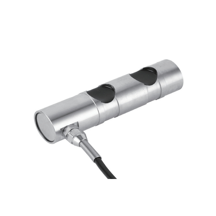
METRAVON MV-LC0226 is a load pin for measuring force transmitted through a supported pin connection. Rated-load options are 2, 3, 5, 10, 20, 30 and 50 t. It provides a bridge output for the defined loading arrangement; it is not a multi-axis sensor reporting separate X, Y and Z forces or independent moments.
Match the load pin to the joint, not just its diameter
The loaded member and outer supports must contact the intended regions of the pin. An incorrect support span changes the internal force distribution. The drawing also defines orientation and retention details; installation must preserve the relationship between the sensing sections and the applied load.
| Rated load | Diameter D | Overall length L |
|---|---|---|
| 2 t | 35 mm | 139 mm |
| 3, 5 t | 40 mm | 160 mm |
| 10 t | 50 mm | 205 mm |
| 20 t | 70 mm | 255 mm |
| 30 t | 85 mm | 290 mm |
| 50 t | 105 mm | 356 mm |
Use this table to identify the relevant size group. A replacement decision also needs the full drawing of the support widths, bearing positions, retaining hardware and cable outlet. Enlarging a hole or adding a sleeve without checking the load-transfer arrangement can invalidate the intended measurement geometry.
Calibrate to the individual pin's bridge output
| Signal or service parameter | Specification |
|---|---|
| Rated sensitivity | 1.5 ±0.5 mV/V |
| Total error | ±0.5% FS |
| Input / output resistance | 700 ±10 / 702 ±2 ohm |
| Excitation | 4-12 V DC; maximum 15 V DC |
| Operating temperature | -30 to +70 °C |
| Safe overload / protection | 150% FS / IP67 |
| Cable | Four-wire, 6 m, 6 mm diameter |
The stated sensitivity tolerance is ±0.5 mV/V, not ±0.005 mV/V. Do not treat the nominal 1.5 mV/V value as an individual calibration result. Use the supplied calibration information and a known-load check in the installed joint to establish scaling. Verify that the bridge-input instrument has a suitable adjustment range.
The four bridge leads are red for excitation positive, black for excitation negative, green for signal positive and white for signal negative; the shield is identified separately. A request for 4-20 mA or an RS485 connection needs a specified conditioning device. Those interfaces are not established by the raw mV/V output.
Define what the load-monitoring system must do
State whether the required result is pin reaction, line tension or another calculated machine load. These quantities may differ. For example, a pulley reaction depends on the directions of the forces acting on the pulley, so a displayed rope tension needs the corresponding geometry and scaling.
For overload monitoring, agree the operating load, alarm response and fault handling at system level. The sensor's measurement rating does not certify the complete safety function. Commission the assembled system with the correct pin orientation and record the loading geometry, zero, reference-load readings and unload results.
Load-monitoring questions
Q1. Can this model resolve several force directions independently?
No independent axis outputs or cross-axis calibration matrix are specified for this configuration. Use it for the defined pin-loading arrangement. A project needing separate force or torque components requires a sensor documented for those channels.
Q2. Can a spare pin use the previous sensor's calibration setting?
Not without verification. Sensitivity, seating and support contact can change the relationship between load and output. Identify the spare by its calibration record, then check zero and span after installation before relying on the displayed value or alarm threshold.
Q3. What information is needed before a replacement price is meaningful?
Provide the existing pin and joint drawings, required rated load, calculated maximum reaction, retaining arrangement and cable access. Add the receiving instrument and any alarm requirements so mechanical fit and signal conversion are both included in the review.
Submit an MV-LC0226 load-pin enquiry with the installation drawing and required quantity. Ask the quotation to identify the selected geometry, calibration documentation and any external signal conditioner.
