


 Chinese
 Spanish
 Russian
 Portuguese
 French
 German
 Indonesian
 Thai
 Vietnamese
 Arabic
 Italian
 Turkish
 Polish
 Japanese



METRAVON MV-LC0220 is a single-point load cell for platform weighing, available in 50, 100, 150, 200, 250, 300 and 500 kg versions. The listed body is 150 x 38 x 38 mm, with eight M6-6H fixing features. Its 3 m four-core cable and bridge characteristics should be included in the indicator and enclosure layout before a scale build or replacement is approved.
What belongs in an MV-LC0220 quotation?
Provide the platform drawing, total supported mass, largest product load and likely off-centre load positions. Identify the chosen capacity, material requirement and existing or proposed indicator. Include the cable route and the required calibration record. These details let the quotation address the actual weighing assembly instead of offering a nominally matching load cell with unresolved mounting or wiring.
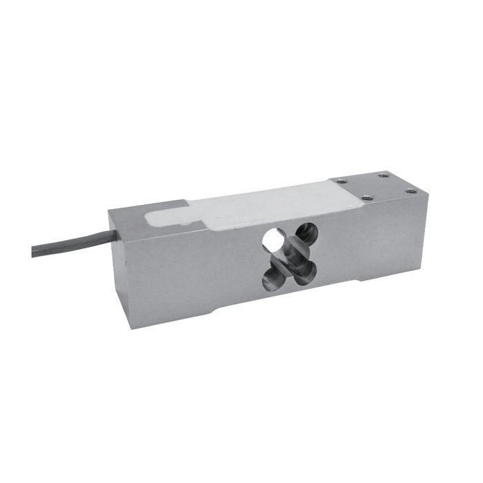
Single-point load cell geometry is more than overall length
Check the two attachment regions and the complete hole pattern, including the 25.4 mm fixing spacing shown on the drawing. Use the selected version's drawing to settle engagement and clearance. Keep the load receptor from touching the fixed base or surrounding guards through its working movement. Do not infer a permitted platform size from the 150 mm sensor length; that limit is not stated in the available sheet.
| Item | Value | Use / fit |
|---|---|---|
| Available ratings | 50, 100, 150, 200, 250, 300, 500 kg | Specify the selected capacity and gross supported load. |
| Input / output resistance | 406 +/-10 / 350 +/-3 ohms | Verify compatibility with the bridge reader. |
| Catalogue total error | +/-0.02% FS | Not the acceptance uncertainty of the completed scale. |
| Creep, 30 minutes | +/-0.016% FS | Include a load-hold check where required by the process. |
| Temperature effects, zero / sensitivity | Each +/-0.02% FS per 10 deg C | Assess the expected temperature change during operation. |
| Working temperature | -30 to +70 deg C | Not a promise of constant system accuracy across that range. |
| Cable | Four-core; 3 m listed | Confirm terminations and the installed route on the order. |
| Housing protection | IP67 | Review material choice and exposed connections separately. |
Understand the rated-output tolerance before reusing gain settings
Rated output is specified as 2.0 +/-0.002 mV/V. That is a sensitivity tolerance, distinct from the +/-0.02% FS total-error entry. It does not remove the need to calibrate the installed scale or establish its usable resolution. A replacement changes the measuring chain, so check zero and known-load results rather than approving it from nominal output alone.
Finish the wiring before final weighing checks
Use a bridge-compatible indicator with 4-12 V DC excitation and a maximum of 15 V DC. The standard 3 m cable is specified for the 50-500 kg options. If the installation needs a different route or an extension, agree the final arrangement before setting span. Test repeated placement, unloading and agreed corner positions with the receptor, guards and cable restraints in their final state.
Compare MV-LC0219 for 50-300 kg applications with a different 35 mm body width and different overload limits; matching length is not enough for substitution.
Indicator and acceptance questions
Q1. Is a smaller sensitivity tolerance the same as a better scale division?
No. The sensitivity tolerance describes how closely the output scale factor matches the nominal value. The smallest reliable displayed weight also depends on noise, mounting, vibration, load-cell behaviour and calibration. Define and verify the required weighing performance at system level.
Q2. Can this sensor provide Modbus RTU directly?
No direct digital output is documented for this configuration. Use a weighing instrument or transmitter with a compatible bridge input, then specify and verify the required communication interface on that separate device.
Q3. What should be checked when the load will remain on the platform?
Agree the hold duration, warm-up and zeroing procedure and the permitted indication change. Record results under the actual loading arrangement. The 30-minute creep entry alone does not define acceptance for every process duration.
