


 Chinese
 Spanish
 Russian
 Portuguese
 French
 German
 Indonesian
 Thai
 Vietnamese
 Arabic
 Italian
 Turkish
 Polish
 Japanese



METRAVON MV-LC0214 is a single-point platform load cell offered at 100, 150, 200, 250, 300, 500 and 800 kg. These are separate nominal ratings, not adjustable settings in one sensor. Selection should account for where the load sits, how it arrives and the supported receptor mass before the receiving instrument is assigned a net weighing range.
Load position can decide platform suitability
Specify the receptor dimensions and the most distant point where the product can be placed. The available sheet does not define a maximum platform size or a permissible eccentric moment. Do not borrow those limits from another model, even where body length and output look similar. Ask for the relevant application assessment before using an overhanging tray or a large package footprint.
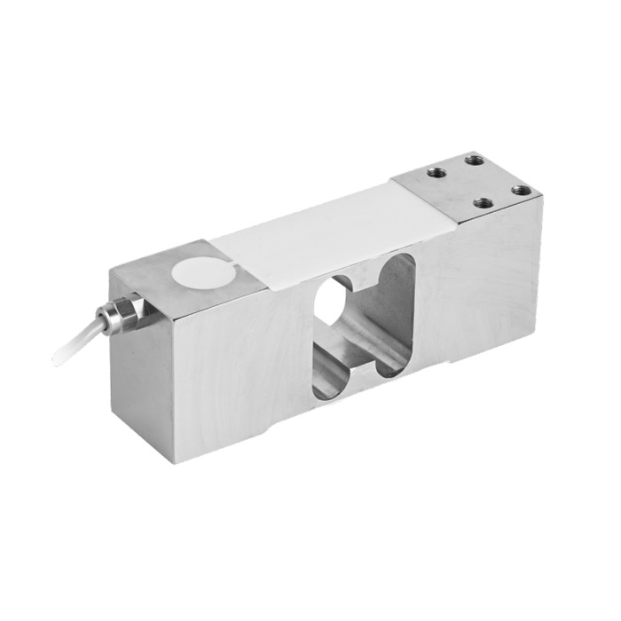
Keep installation forces out of the weighing result
The outline shows a 174 x 60 x 64 mm body and eight M8-6H fixing features. Use the selected drawing to check attachment faces, positions and engagement. Guides, covers or transfer parts must not support a changing fraction of the receptor load. Look for contact throughout the expected movement, including after fasteners and guards are secured.
Single-point load cell wiring and control integration
The standard cable is four-core and 2 m long for the listed 100-800 kg group. Input resistance is 385 +/-10 ohms and output resistance is 350 +/-3 ohms. A weighing indicator or bridge conditioner supplies excitation and reads the millivolt signal. If the process requires 4-20 mA, specify that output on the reading device rather than treating it as a built-in sensor function.
| Item | Value | Use / fit |
|---|---|---|
| Rating steps | 100, 150, 200, 250, 300, 500, 800 kg | Select from the listed options; do not assume a 750 kg version. |
| Nominal output | 2.0 +/-0.2 mV/V | The actual span needs reference-load calibration. |
| Excitation | 4-12 V DC; maximum 15 V DC | Verify the bridge supply of an existing indicator. |
| Creep over 30 minutes | +/-0.016% FS | Check indication change during any process hold. |
| Safe / destructive entries | 150 / 300% FS | Not an approved operating range beyond nominal capacity. |
| Working temperature | -30 to +70 deg C | Assess the real temperature cycle and weighing requirements. |
| Construction / protection | Material option; IP67 | Confirm material choice and protection of external connections. |
Set the acceptance limits before changing the scale
Agree the useful weighing range, smallest relevant change, repeatability requirement and load-position checks. Then calibrate in the final assembly and retain loaded and unloaded readings. The total-error entry is +/-0.02% FS; a finished scale result also depends on its receptor, mounting and instrument. A high display count alone is not evidence that the weighing task is met.
MV-LC0213 covers 500, 600 and 750 kg options on its product page and has different bridge input data; review it independently if those ratings fit the project better.
Load placement and selection
Q1. Can 800 kg be selected just to cover every future load?
A larger range leaves less signal per kg for the same nominal sensitivity and excitation. Define the lowest useful weighing point as well as the largest gross load, then verify that the selected reader and mechanical assembly meet both needs.
Q2. What if the load enters from a filling chute?
Include the drop conditions, receptor movement and any chute contact in the mechanical review. Catalogue overload percentages do not state an allowable drop height or guarantee performance during impact. Verify readings under the intended settled weighing condition and agree any protection needed.
Q3. What should be included when comparing quotations?
Compare the selected rating, material, complete mounting drawing, cable and reader arrangement, plus the required calibration and position tests. A quote that only matches capacity and nominal output leaves important installation questions unanswered.
