


 Chinese
 Spanish
 Russian
 Portuguese
 French
 German
 Indonesian
 Thai
 Vietnamese
 Arabic
 Italian
 Turkish
 Polish
 Japanese



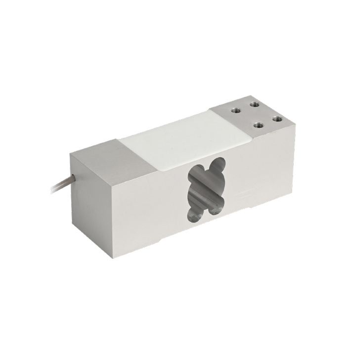
METRAVON MV-LC0213 is a single-point platform load cell offered at 500, 600 and 750 kg. The dimensional outline is 174 mm long, 60 mm wide and 64 mm high. At these ratings, the load receptor and supporting frame remain part of the measurement: increasing sensor capacity cannot compensate for an unstable base or an uncontrolled load path.
Separate sensor rating from usable product capacity
Count the receptor and all supported attachments before assigning the maximum net product weight. Describe the loading method, including any material impact or placement shock. A heavier frame can consume more of the rated load than expected, while tare adjustment only changes the indication. Obtain the permitted platform dimensions and eccentric-load conditions for the selected configuration; neither limit is stated on the available sheet.
| Item | Value | Use / fit |
|---|---|---|
| Published options on this page | 500, 600, 750 kg | Confirm the selected configuration and its drawing on the quotation. |
| Rated sensitivity | 2.0 +/-0.2 mV/V | Requires individual calibration of the installed assembly. |
| Input / output resistance | 406 +/-10 / 350 +/-3 ohms | Match the bridge instrument and excitation capability. |
| Excitation range | 4-12 V DC; maximum 15 V DC | A separate measuring device is needed for control-system outputs. |
| Catalogue total error | +/-0.02% FS | Not the error limit of the whole platform scale. |
| Working temperature | -30 to +70 deg C | Assess temperature changes during the weighing cycle. |
| Cable qualification | 600 / 750 kg: confirmation required | Do not extend the 50-500 kg cable note to higher options. |
| Ingress rating | IP67 | Identify material choice and terminal protection independently. |
Mounting the 174 mm single-point load cell
The drawing identifies eight M8 fixing features. Compare their positions, the supporting faces and engagement requirements with the actual frame. Keep the moving receptor clear of the base, access covers and neighbouring equipment. If an old mounting adapter is retained, check that it does not bridge the sensing region or cause the load to enter through an unintended contact.
Confirm the cable for 600 and 750 kg
The cable note specifies a four-core 2 m cable for 50-500 kg. It therefore does not confirm the delivered cable for the 600 or 750 kg options covered here. Ask for the capacity-specific cable and termination details before choosing the indicator location. A joint that must be added during installation introduces its own moisture protection and calibration requirements.
Use a controlled loading sequence for acceptance
Check the completed scale with reference loads suited to the working range. Record increasing and decreasing loads, repeated placement and the agreed load positions on the receptor. When the process leaves material on the scale, include a sustained-load check. The +/-0.016% FS creep entry is specified over 30 minutes; acceptance for a different process duration needs an agreed test.
Review MV-LC0214 for its different published capacity steps, bridge input resistance and selected drawing; a similar outer size is not proof of equivalence.
Capacity and acquisition questions
Q1. Can a 750 kg version support an arbitrarily large receptor?
No maximum receptor size is specified here. Supply its dimensions, stiffness arrangement and loading positions for review. A load below 750 kg does not, by itself, establish acceptable off-centre performance.
Q2. Is a raw 2 mV/V bridge an RS485 sensor?
No. For digital recording, select an indicator or bridge acquisition module that provides the required interface. Confirm its actual protocol, channel scale factor and fault indication separately from the load cell.
