


 Chinese
 Spanish
 Russian
 Portuguese
 French
 German
 Indonesian
 Thai
 Vietnamese
 Arabic
 Italian
 Turkish
 Polish
 Japanese



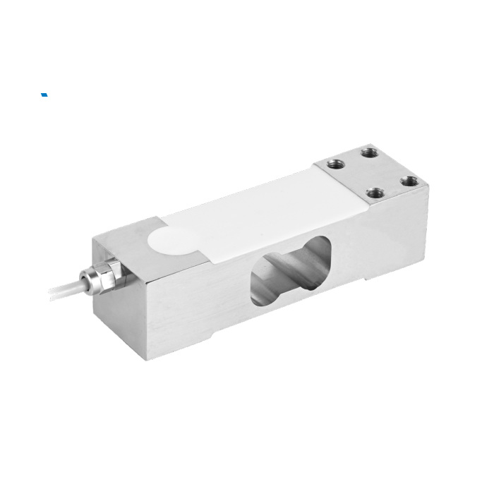
METRAVON MV-LC0212 is a single-point load cell with 50, 100, 150, 200, 250, 300 and 500 kg options. For an existing scale, the main purchasing question is whether its mounting and bridge input match the proposed replacement. A shared capacity and a nominal 2 mV/V output are not enough to preserve either mechanical fit or the previous calibration.
Start with the reason the old scale failed
Before ordering a replacement, inspect the receptor for contact with the frame, loose supports, water-damaged terminals and cable strain. These faults can change the indication even when the sensing element is serviceable. Record the symptoms and the conditions in which they appear. Replacing a sensor while leaving a rubbing guard or an unstable base in place may leave the fault unchanged.
Compare the single-point load cell drawing and bridge data
The nominal body is 150 mm long, 44 mm wide and 40 mm high, with eight M6-6H fixing features. Compare the old drawing with the attachment faces, hole locations and available screw engagement. Electrically, this version lists 385 +/-10 ohms input resistance and 350 +/-3 ohms output resistance. Those are different from MV-LC0211 despite the similar outline.
Keep cable work separate from calibration adjustment
The published configuration lists a 2 m four-core cable. If the existing indicator is farther away, agree the connection method and environmental protection before installing the sensor. Do not use a new zero or span setting to conceal an intermittent joint. Complete the wiring and cable restraints, allow the instrument setup to settle according to its instructions, then calibrate using reference loads.
| Item | Value | Use / fit |
|---|---|---|
| Rating choices | 50, 100, 150, 200, 250, 300, 500 kg | Confirm gross supported load rather than matching a display label. |
| Nominal sensitivity | 2.0 +/-0.2 mV/V | Recheck span even if the old sensor also stated 2 mV/V. |
| Excitation | 4-12 V DC; maximum 15 V DC | Check the indicator's actual bridge supply. |
| Cable | Four-core; 2 m listed | Protect terminations for the installation environment. |
| Creep, 30 minutes | +/-0.016% FS | Consider the actual duration of loaded weighing. |
| Overload entries | 150% safe; 200% destructive | Do not use either as a routine weighing capacity. |
| Construction / ingress | Material option; IP67 | A metal-looking housing does not identify the ordered alloy. |
A replacement is accepted in the scale, not on the bench
Compare unloaded readings, multiple loaded points and zero after unloading. Move the same reference weight to the agreed positions to identify receptor or mounting effects. Set acceptable limits from the weighing task and instrument requirements; the catalogue total-error value of +/-0.02% FS is a sensor specification. Retain the new settings and results so later maintenance can identify what changed.
Compare MV-LC0211 only after checking its 406 ohm nominal input resistance and selected-version mounting details.
Replacement decisions
Q1. Can the existing calibration values be copied to the replacement?
They may be useful as a setup reference, but cannot serve as acceptance. The individual sensitivity, cable conditions and mounted zero can differ. Verify the installed replacement with known loads before production use.
Q2. When is a material change relevant to the order?
State the required material whenever cleaning, moisture or corrosion exposure matters. The data lists construction alternatives, not a guarantee that every unit is stainless steel. Confirm the delivered version and the protection of the separate terminal enclosure.
Q3. What is needed to compare an old sensor from another manufacturer?
Provide its nameplate, drawing, cable identification and electrical data, together with the receptor load and scale symptoms. Any replacement decision must compare geometry and the measuring channel; an old model name alone does not establish interchangeability.
