


 Chinese
 Spanish
 Russian
 Portuguese
 French
 German
 Indonesian
 Thai
 Vietnamese
 Arabic
 Italian
 Turkish
 Polish
 Japanese



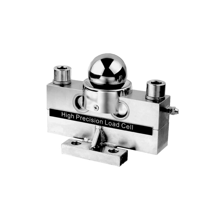
METRAVON MV-LC0201 is a shear beam load cell shown with a spherical load contact and mounting structure for truck-scale or weighing-module assemblies. Ratings are 10, 15, 20, 25, 30 and 40 t. Selection needs the complete contact and support arrangement, not only a sensor capacity; identify which mechanical parts are included in the proposed supply.
Check the spherical contact and capacity-specific height
The table gives H = 224.7 mm for 10-30 t and H = 230.7 mm for 40 t. The spherical diameter D2 is 76.2 mm, while D1 is shown as 85-88 mm for the lower group and 88 mm for 40 t. Obtain the selected drawing to settle the actual contact and mounting dimensions. A 40 t unit cannot be approved against the lower group's height simply by changing the indicator range.
| Item | Value | Use / fit |
|---|---|---|
| Capacity choices | 10, 15, 20, 25, 30, 40 t | Select the version from the highest relevant support reaction. |
| Overall height H | 224.7 mm: 10-30 t; 230.7 mm: 40 t | Check height against the surrounding load-introduction hardware. |
| Spherical diameter D2 | 76.2 mm | Use the full selected drawing for the mating contact. |
| Excitation | 4-12 V DC; maximum 15 V DC | The bridge requires a suitable measuring input. |
| Creep over 30 minutes | +/-0.02% FS | Define load-hold conditions for the acceptance procedure. |
| Working temperature | -30 to +70 deg C | Review the actual temperature at the installed sensor. |
| Material / protection | Alloy steel / IP68 listed | Confirm the relevant ingress conditions for the ordered configuration. |
The shear beam load cell is part of a mechanical assembly
Provide the foundation, supporting members, upper contact and restraints together. The sphere is a load-introduction feature, not a documented allowance for unrestricted sideways movement or uplift. Check the maximum reaction at the measuring point with the intended deck positions. Include foundation movement and the condition of existing contact surfaces when reviewing a replacement installation.
Match the 2 mV/V bridge and the 16 m cable
The listed output is 2.0 +/-0.002 mV/V, with input resistance of 760 +/-10 ohms and output resistance of 702 +/-2 ohms. At 10 V excitation the nominal rated signal is about 20 mV; this is not a 0-10 V output. The documented cable is four-core and 16 m long across the 10-40 t group. Confirm the actual reader input and final cable arrangement before calibration.
Agree the installed checks and environmental conditions
Verify zero, reference-load response and the agreed positions after the contacts are seated and the cable is secured. Record unloaded return and repeated loading. IP68 is listed, but the available sheet does not give an immersion depth and duration. Request the applicable test conditions and connection protection if standing water or immersion is part of the installation.
MV-LC0202 lists a shorter double-shielded cable; review its complete configuration rather than treating the two codes as an automatic swap.
Contact and assembly questions
Q1. Does the pictured assembly define everything supplied?
Not without a confirmed scope of supply. Identify the sensor, contact components, base or mounting parts and fasteners on the quotation. The installation drawing and supplied items must agree before site work begins.
Q2. Can C3 be treated as approval of the whole truck scale?
The sensor classification does not approve a completed weighing system. Request the required model-specific documentation and agree the scale acceptance or conformity requirements separately. Do not infer a finished-scale division or approval from the catalogue entry alone.
