


 Chinese
 Spanish
 Russian
 Portuguese
 French
 German
 Indonesian
 Thai
 Vietnamese
 Arabic
 Italian
 Turkish
 Polish
 Japanese



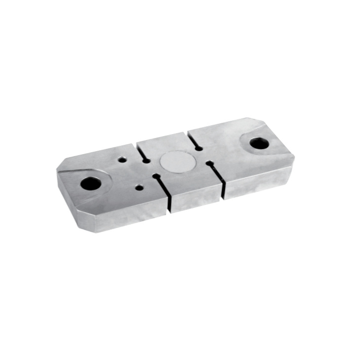
METRAVON MV-LC0200 is a flat tension load cell with 5 t and 10 t ratings for tensile-force measurement and hanging-scale assemblies. The two ratings use different body lengths, main-hole diameters and thickness dimensions. A 10 t selection therefore requires a review of the force-carrying hardware, not simply a higher range setting in the indicator.
5 t and 10 t use different connection geometry
For 5 t, the drawing gives A = 255 mm, main-hole diameter D = 22 mm and thickness dimensions H1/H2 = 30/28 mm. At 10 t these become 295 mm, 28 mm and 40/38 mm. Use the complete selected drawing to check the mating pins, contact surfaces and available space. Do not use a loosely fitting smaller pin or assume the existing bearing arrangement carries the higher rating.
| Item | Value | Use / fit |
|---|---|---|
| Rated versions | 5 t / 10 t | Confirm the version with its matching drawing. |
| Overall length A | 255 mm / 295 mm | A rating increase changes the installed envelope. |
| Main-hole diameter D | 22 mm / 28 mm | Pin and bearing design require the full mechanical review. |
| Thickness H1 / H2 | 30 / 28 mm: 5 t; 40 / 38 mm: 10 t | Check the mating clearances for the ordered rating. |
| Standard cable | Four-core, 12 m | Complete routing and termination before zero and span setup. |
| Excitation | 4-12 V DC; maximum 15 V DC | Confirm the instrument supports the low-level bridge. |
| Construction / environment | Alloy steel / IP67 | Working temperature is -30 to +70 deg C. |
Review the complete force path before hanging a load
Provide the end connections and their supports, the load direction and how the assembly is retained if a connection fails. Include attachment weight and foreseeable peak tension. Avoid fixtures that bridge the sensing slots or introduce lateral contact. Safe overload is listed as 150% FS and ultimate overload as 200% FS; neither documents acceptable snatch loading, a lifting approval or an operating load above the sensor rating.
Connect the 12 m bridge cable before calibrating
The specified four-core cable is 12 m long for both ratings. Nominal output is 2.0 +/-0.002 mV/V, with input resistance 385 +/-10 ohms and output resistance 350 +/-2 ohms. Check reader excitation capacity and signal range with the final wiring in place. An output requirement such as 4-20 mA needs separately specified conditioning; the bare sensor does not provide that signal.
Verify the tensile system in its working arrangement
Use an agreed reference-loading procedure that keeps personnel clear of the loaded assembly. Check several load points, repeated readings and zero after unloading, with the final contacts seated. The sensor total-error entry is +/-0.05% FS, while the 30-minute creep entry is +/-0.03% FS. For a long-held load, verify the required hold behaviour rather than accepting the system from one brief span reading.
Higher-load replacement decisions
Q1. Can a 5 t assembly be upgraded by fitting the 10 t sensor?
Not without checking the surrounding hardware. Hole diameter, length and thickness all change, and the connections or supports may still be rated for the old load. Approve the complete modified assembly and its verification procedure before increasing service tension.
Q2. Does the 12 m cable guarantee compatibility with the old indicator?
Cable length alone says nothing about the indicator input or previous calibration. Compare bridge excitation, signal range, wiring identification and the required display units. After replacement, establish zero and span with the installed cable and representative reference loading.
