


 Chinese
 Spanish
 Russian
 Portuguese
 French
 German
 Indonesian
 Thai
 Vietnamese
 Arabic
 Italian
 Turkish
 Polish
 Japanese



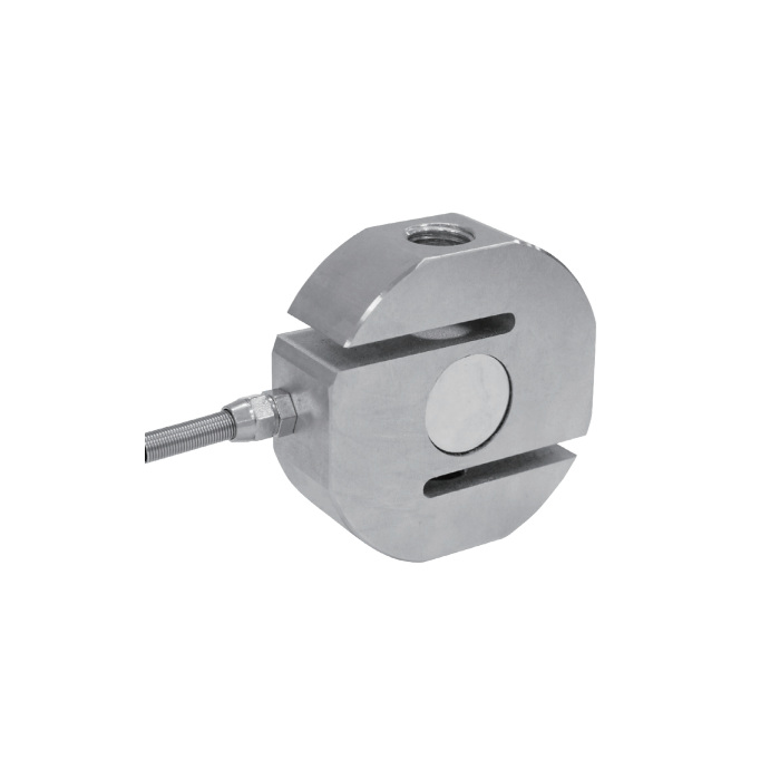
METRAVON MV-LC0187 is a compact S-type load cell offered at 1, 1.5 and 2 t for suspended weighing and tensile measurement. The drawing specifies M18 x 1.5 connections, a 76 mm body height and 26 mm thickness. Select it where that complete connection envelope suits the linkage, including room for the side cable exit and mating attachments.
Compact S-type load cell fit includes the attachments
A small sensor body does not establish a short assembled linkage. Add the length of the adjoining threaded parts and any adjustment hardware when checking the installed distance. Confirm thread engagement, strength and clearance against the full drawing. Keep the force along the connection axis and ensure adjacent parts remain clear of the slotted body during loading; do not use the outer contour as an unintended bearing surface.
| Item | Value | Selection notes |
|---|---|---|
| Capacity choices | 1, 1.5, 2 t | Choose one rating for the actual applied tension. |
| Thread connection | M18 x 1.5 | Check the mating part, engagement and available adjustment. |
| Body height / thickness | 76 / 26 mm | Include the cable exit and all attachment clearances. |
| Standard lead | Four-core, 3 m; 6 mm diameter | Plan the protected connection and avoid cable restraint. |
| Excitation range | 4-12 V DC; maximum 15 V DC | The raw bridge is not a 0-10 V industrial output. |
| Overload entries | 150% safe / 300% ultimate | Neither entry establishes a routine overload allowance. |
| Environment | Alloy steel; IP67; -30 to +70 deg C | Review the actual exposure and the external cable joints. |
Wire the 3 m bridge lead before setting the display range
The standard cable is four-core, 3 m long and 6 mm in diameter. Its termination needs strain relief that does not pull on the measuring body. The reader must support a bridge rated at 2.0 +/-0.002 mV/V. Electrical resistance is specified as 385 +/-10 ohms at the input and 350 +/-2 ohms at the output. Complete the intended cable and reader connection before calibration. If a remote enclosure requires a longer route, identify that requirement before the order rather than assuming an extension is included.
Use the required force interval to define acceptance
Total error is listed as +/-0.02% FS, and the 30-minute creep entry is also +/-0.02% FS. These describe sensor specifications, not the combined error of the sensor, threaded linkage and reader. Check zero after fitting the attachments, apply reference loads through the working interval and repeat the readings after unloading. For a sustained suspended load, agree how long it must be held and what indication change is acceptable at system level.
Instrument and construction questions
Q1. Does this provide a direct PLC current signal?
The documented output is expressed in mV/V and needs bridge excitation and a suitable measuring input. If the control system requires 4-20 mA, specify a compatible weighing amplifier or transmitter and confirm its supply, scaling and fault behaviour separately.
Q2. Is stainless steel one of the listed material choices?
This model is specified in alloy steel. Do not order it as a stainless version based on descriptions of other S-type products. Explain the corrosion and cleaning conditions so that the offered construction can be checked before purchase.
Q3. Does the 300% ultimate-overload entry justify a lifting load?
It does not approve the complete lifting assembly or define a service load above the rated measuring capacity. The designer must assess all load-bearing parts, retention and consequences of failure. Obtain any application-specific documentation required for that assembly rather than relying on one overload number.
