


 Chinese
 Spanish
 Russian
 Portuguese
 French
 German
 Indonesian
 Thai
 Vietnamese
 Arabic
 Italian
 Turkish
 Polish
 Japanese



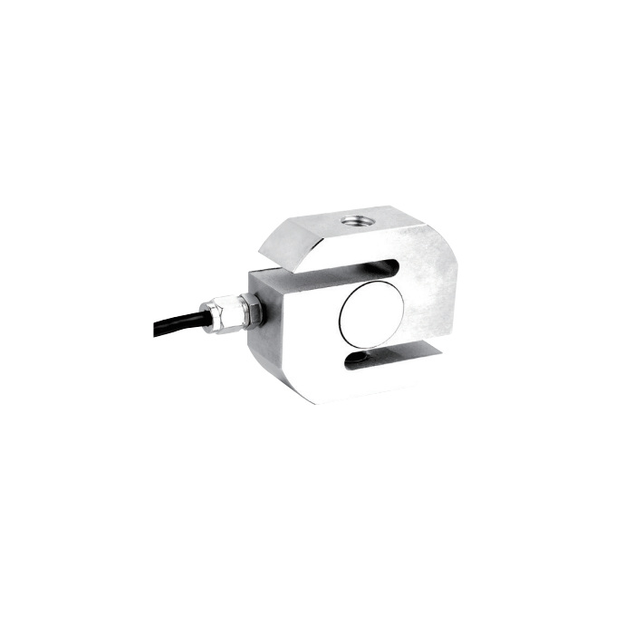
METRAVON MV-LC0186 is an S-type load cell covering discrete ratings from 20 kg to 10 t for hanging scales and tensile tests. It is not one body with an adjustable measuring range: the drawing groups change thickness, height and threaded connections. Establish the load rating and installed envelope together before deciding whether existing attachments can remain.
Select the S-type load cell from its actual dimensional group
For 20-150 kg, thickness L is 12 mm, dimension H is 64 mm and the connection is M8. At 200-500 kg, L becomes 20 mm with M12 threads, while 700-1000 kg uses L = 25 mm with M12. The 1.2-5 t group moves to L = 32 mm, H = 90 mm and M20. At 7.5 t, L is 40 mm with M24; 10 t uses L = 50 mm, H = 110 mm and M32 x 2. Obtain the full selected drawing for thread engagement and clearance; pitches are not stated for every listed thread size.
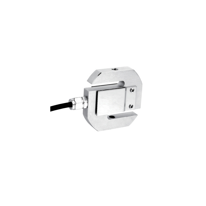
Check what the cable note covers before placing the reader
The standard four-core cable is listed as 3 m for 20 kg through 1 t, 5 m for 2-7.5 t and 8 m for 10 t. The 1.2 t and 1.5 t choices are not assigned a length by that note. Ask for their delivered cable configuration rather than interpolating. Plan access to the electrical connection without making the cable restrain the body or carry any part of the suspended force.
Match bridge excitation and verify the useful working interval
Rated sensitivity is 2.0 +/-0.002 mV/V, input resistance is 385 +/-10 ohms and output resistance is 351 +/-2 ohms. The selected reader must excite the bridge and measure its small differential signal. A higher sensor capacity reduces the fraction of full-scale output produced by a given working load. Verify the lowest force that matters to the process as well as the upper working point; do not select only from the largest available rating.
| Item | Value | Selection notes |
|---|---|---|
| kg options | 20, 30, 50, 75, 100, 150, 200, 300, 500, 700 kg | Use the discrete rating, not every value between endpoints. |
| t options | 1, 1.2, 1.5, 2, 2.5, 3, 5, 7.5, 10 t | Check thickness and connections after choosing the force rating. |
| Low-range body group | 20-1000 kg | Several thicknesses and thread sizes exist within this group. |
| Excitation voltage | 4-12 V DC; maximum 15 V DC | Confirm that the reader supports the installed bridge. |
| Safe / ultimate overload | 150 / 200% FS | No shock or lifting-duty approval is established by these entries. |
| Working temperature | -30 to +70 deg C | Evaluate temperature where the sensor is actually installed. |
| Material / protection | Steel options / IP67 | State the required material and protect external terminations separately. |
Inspect the linkage before recording acceptance readings
Align the threaded attachments and ensure adjoining parts do not contact the sensing slots. Include attachment weight and expected force peaks in the selection review. Once assembled, record reference loads, repeated indications and unloaded return. Where tension remains applied, include a hold period relevant to the duty; the 30-minute creep entry is +/-0.02% FS. C3 is a sensor classification, not a statement that the complete hanging scale meets a particular approval.
For a compact 1-2 t arrangement, review MV-LC0187 with its own M18 x 1.5 connection and body geometry; the two models do not share a universal mounting.
Capacity changes and existing attachments
Q1. Will a 1.2 t sensor fit in the same space as a 1 t sensor?
They belong to different drawing groups. The listed thickness changes from 25 mm at 1 t to 32 mm in the 1.2-5 t group, and the thread changes from M12 to M20. Review the full assembly rather than assuming a small capacity increase keeps the same fittings.
Q2. Can the catalogue photograph identify the version to order?
The photographs show different body profiles within the product family. Use the selected capacity and dimensional drawing to identify the version; the picture alone does not establish its thread, thickness, material or cable length.
Q3. What should I send when replacing an existing suspended sensor?
Provide the old rating, thread details, installed length and available thickness clearance. Include the reader model, wiring identification, cable route and required load interval. These details allow the proposed version to be checked against both the mechanical assembly and measurement requirements.
