


 Chinese
 Spanish
 Russian
 Portuguese
 French
 German
 Indonesian
 Thai
 Vietnamese
 Arabic
 Italian
 Turkish
 Polish
 Japanese



METRAVON MV-LC0185 is a compression load cell for vessel weighing and compressive-force testing. It lists 100, 200, 300 and 500 klb configurations and 50, 100, 150 and 250 t configurations. These options use different fixing-thread systems and need a unit-confirmed installation drawing; the working temperature is -10 to +40 deg C, not the wider range of several adjacent models.
Keep the fixing thread and dimensional units with the chosen version
The imperial-capacity rows specify 3/4-16 UNF fixing threads, with depth entries that differ by group. The metric-capacity rows specify M20 x 1.5, with 15 mm depth at 50 t and 20 mm at 100-150 t and 250 t. Obtain a drawing that explicitly identifies the units and dimensional endpoints before manufacturing mating parts. Do not mix numbers from the two sets of rows or assume that an imperial rating is an exact metric substitute.
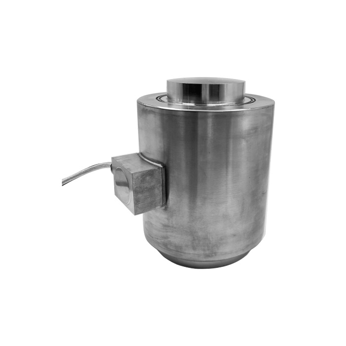
Check the compression load cell temperature and material requirements
The listed working range is -10 to +40 deg C. Assess actual sensor exposure, including process heat and the lowest site temperature, before selecting a version. IP68 is listed, but the available model specification does not establish the construction material or an immersion depth and duration. Put material, corrosion exposure and any water conditions into the enquiry and obtain the offered construction in writing.
Confirm the rated output and measuring-channel configuration
Nominal sensitivity is 1.75 mV/V. Obtain a confirmed sensitivity tolerance and calibration data for the ordered version; a percentage tolerance and an absolute mV/V tolerance are not the same specification. The bridge input resistance is 750 +/-10 ohms and output resistance 700 +/-5 ohms. Cable length is not established by the model table, so confirm its delivered configuration together with reader excitation, input range and final route.
| Item | Value | Selection notes |
|---|---|---|
| klb configurations | 100, 200, 300, 500 klb | Confirm the selected imperial drawing and thread depth. |
| t configurations | 50, 100, 150, 250 t | Specify the required rating with its original capacity unit. |
| Metric fixing connection | M20 x 1.5 | Depth is 15 mm at 50 t and 20 mm in the higher metric groups. |
| Imperial fixing connection | 3/4-16 UNF | Obtain explicit units and engagement depth from the selected drawing. |
| Nominal sensitivity | 1.75 mV/V | Confirm the tolerance and actual calibration data before ordering. |
| Excitation / temperature | 4-12 V DC / -10 to +40 deg C | Maximum excitation is 15 V DC; the site temperature must suit this range. |
| Safe / ultimate overload | 150 / 200% FS | Neither figure extends the rated measuring range or approves an unreviewed support assembly. |
Use nonlinearity, hysteresis and creep as different checks
The listed nonlinearity is +/-0.05% FS, hysteresis +/-0.03% FS and 30-minute creep +/-0.03% FS. Those figures describe different sensor behaviours rather than one guaranteed installed-system error. For a vessel, agree repeated filling or reference-loading points and unload return with the complete support structure. For a compression test fixture, define the load direction and reference method before accepting the channel.
Drawing units and replacement checks
Q1. Can a 100 klb unit replace the 50 t version without changing the mounting?
No. The nominal loads differ, and the mounting rows use different thread systems. A 100 klb version lists 3/4-16 UNF, whereas the 50 t row specifies M20 x 1.5 with a 15 mm thread depth. Verify the required rated load, contact geometry and complete unit-confirmed drawing before retaining or machining mounting parts.
Q2. Is +/-0.05% FS the complete vessel weighing accuracy?
That entry is nonlinearity, not a combined system guarantee. Hysteresis, creep, support mechanics, reader performance and the reference-loading method also matter. Set the project acceptance criteria for the installed assembly and test them under the agreed conditions.
Q3. What is needed before approving replacement mounting parts?
Provide the ordered rating with units, the old and proposed drawings, fixing-thread diameter and pitch, engagement depth and contact geometry. Include material and temperature requirements. Resolve all dimensional units explicitly before machining or approving retained parts.
