


 Chinese
 Spanish
 Russian
 Portuguese
 French
 German
 Indonesian
 Thai
 Vietnamese
 Arabic
 Italian
 Turkish
 Polish
 Japanese



METRAVON MV-LC0183 is a compression load cell with a nominal 1.75 mV/V bridge output. Listed ratings are 50 or 100 klb and 23 or 45 t for vessel, silo and test-machine arrangements. The exact nameplate rating, illustrated contact assembly and reader input must agree with the installation specification.
Allow for a lower signal than a 2 mV/V bridge
At 10 V excitation, nominal output at rated load is about 17.5 mV. A 2 mV/V bridge would nominally give 20 mV under the same excitation, so an existing calibration should not be copied. The specified sensitivity is 1.75 +/-0.02 mV/V, with 590 +/-10 ohms input resistance and 480 +/-2 ohms output resistance. Verify the actual reader input, excitation supply and calibration adjustment before accepting the electrical replacement.
Review the compression load cell and contact pieces together
The reference drawing distinguishes a 236 mm assembly height from shorter body dimensions of 184 and 170 mm, and shows 76 mm diameter mating pieces at the ends. Identify the dimensional endpoints and the parts included in the offer before setting the installation height. The appearance of surrounding rings or contact parts does not document an uplift rating, unrestricted joint travel or a complete weighing module.
| Item | Value | Selection notes |
|---|---|---|
| Rating labels | 50, 100 klb; 23, 45 t | Confirm one rating and the intended display units. |
| Rated sensitivity | 1.75 +/-0.02 mV/V | Review input headroom, actual sensitivity and scale factor. |
| Bridge input / output | 590 +/-10 / 480 +/-2 ohms | Different from adjacent compression models. |
| Reference assembly height | 236 mm | Check whether the quoted configuration includes the illustrated contacts. |
| Standard lead | Four-core, 14 m; 6 mm diameter | Complete wiring before verifying the final measuring channel. |
| Excitation | 4-12 V DC; maximum 15 V DC | No direct current-loop or serial output is specified. |
| Working conditions | -30 to +70 deg C; IP68 listed | Confirm the material version and relevant ingress test conditions. |
Choose the ordered rating without assuming exact unit equivalence
The published klb and t options must remain explicit in the selection record. The 23 t and 45 t options should not be treated as exact equivalents of 50 klb and 100 klb. Obtain the ordered nameplate rating and reference-loading requirements. For vessel supports, check how changing fill levels and connected services alter the reaction at each measuring point.
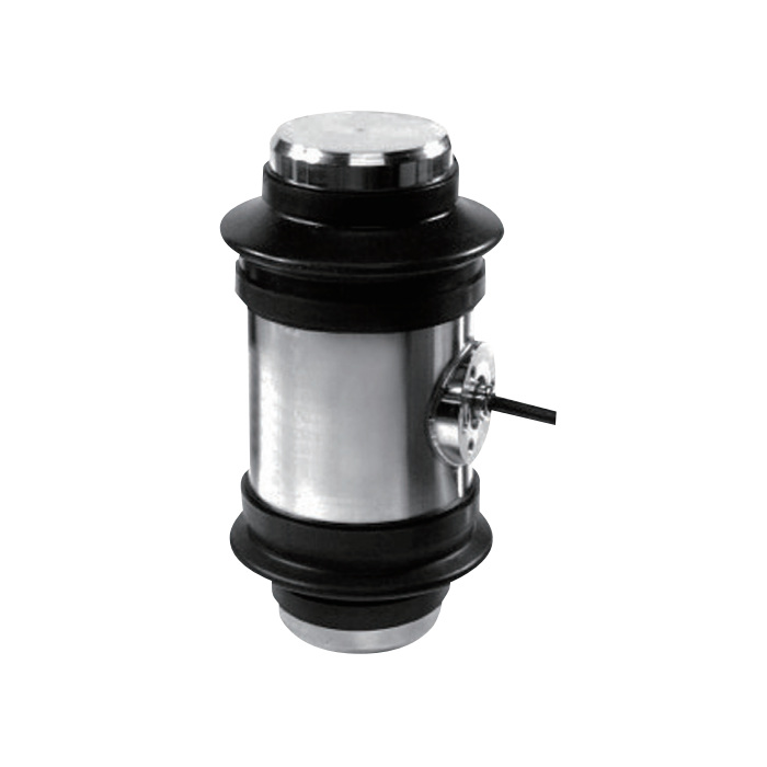
Commission with the final cable and mechanical restraints
A four-core 14 m cable is listed for the stated ratings. Finish its protected route and terminations before calibration, keeping it free of the contact load path. During the installed test, record zero, reference loads, repeat loading and unloaded return. The 30-minute creep entry is +/-0.02% FS; agree any hold check and investigate contact binding before adjusting display filtering.
Signal scaling and contact assembly
Q1. Can the original 2 mV/V indicator setting be retained?
Only if the channel is correctly reconfigured and verified for the actual 1.75 mV/V sensor. Check the excitation, rated signal and connected resistance, then establish the installed zero and span using suitable references. The unchanged capacity label does not justify keeping an old span value.
Q2. Does the 236 mm figure describe the bare sensor only?
The drawing shows the sensor with mating contact pieces and includes shorter internal height dimensions. Confirm the boundaries of the ordered assembly and obtain its installation drawing. Do not reserve site space or fabricate supports from an assumed bare-sensor height.
Q3. Which details are needed when retaining an old support frame?
Provide contact shapes, installed height, surrounding clearances, restraints and the old nameplate. Add the largest support reaction, reader model and final cable route. Check the revised complete assembly before retaining any worn or mismatched contact hardware.
