


 Chinese
 Spanish
 Russian
 Portuguese
 French
 German
 Indonesian
 Thai
 Vietnamese
 Arabic
 Italian
 Turkish
 Polish
 Japanese



METRAVON MV-LC0182 is a column compression load cell for 50, 100 and 120 klb applications, including hopper, silo and test-machine weighing arrangements. Here klb denotes thousands of pounds, not tonnes. The bridge resistance and contact geometry are important replacement checks even when an existing sensor also carries a nominal 2 mV/V label.
Check bridge loading before retaining the old indicator
Input resistance is specified as 1150 +/-10 ohms and output resistance as 1050 +/-10 ohms. These are not the common 350 ohm or 700 ohm values that an installer might expect from another load-cell family. If several bridges share an excitation supply, assess the complete connected load and wiring against the reader specifications. Similar rated sensitivity alone does not establish that the old instrument setup or junction-box adjustments can remain unchanged.
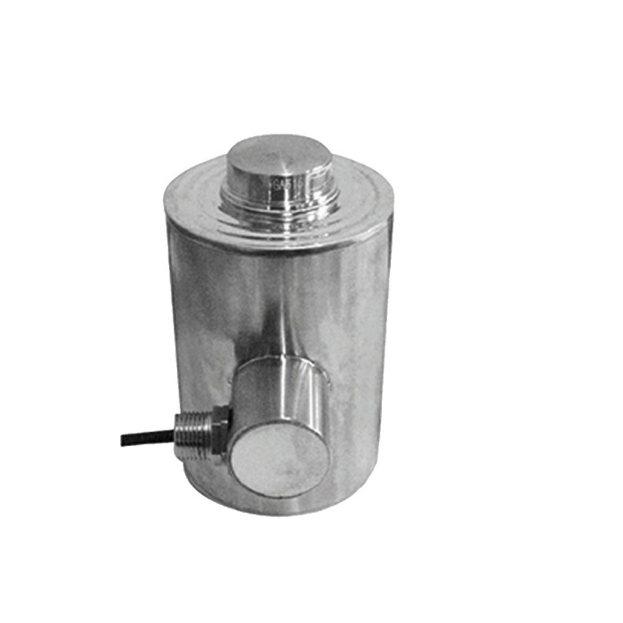
Column compression load cell installation needs both contact details
The reference drawing shows 184.2 mm overall height, a 146 mm central-body height and a 44.5 mm upper contact diameter. Include the lower contact, surrounding supports and side cable access in the mechanical review. Contact surfaces must transfer the intended axial force without interference from the surrounding frame. The drawing does not establish a universal interchangeable base or a permitted amount of lateral movement.
Keep klb ratings and channel calibration consistent
Specify 50, 100 or 120 klb explicitly on the order and record the engineering units used by the measuring channel. The listed signal is 2.0 +/-0.002 mV/V through a four-core 14 m cable. Calibrate the final installation with reference loading appropriate to the supported equipment. A capacity number entered into the indicator without the correct unit and scale factor can produce a plausible but incorrect reading.
| Item | Value | Selection notes |
|---|---|---|
| Capacity options | 50, 100, 120 klb | Do not interpret the capacity numbers as metric tonnes. |
| Nominal input resistance | 1150 +/-10 ohms | Calculate the excitation demand for all connected bridges. |
| Output resistance | 1050 +/-10 ohms | Check the reader and any retained junction-box circuitry. |
| Overall height | 184.2 mm | Verify upper and lower mating interfaces using the full drawing. |
| Cable | Four-core, 14 m; 6 mm diameter | Protect the route and terminate before final calibration. |
| Excitation / temperature | 4-12 V DC / -30 to +70 deg C | Maximum excitation is 15 V DC. |
| Safe / ultimate overload | 150 / 200% FS | These figures are not a rated service range above capacity. |
Check the vessel and connections during acceptance
Observe empty return, repeated loading and the influence of piping or restraints after the contacts are seated. Where a load remains applied, include the required observation period rather than relying on a brief span point; the published 30-minute creep is +/-0.02% FS. Confirm the actual alloy-steel or stainless-steel construction and protection of the completed cable terminations for the site.
MV-LC0181 has metric ratings and different height and bridge data; compare it as another compression configuration, not as an automatic replacement.
Bridge compatibility and rating units
Q1. Can an existing 350 ohm sensor be replaced just because both outputs are 2 mV/V?
Compare the bridge input and output resistances, actual sensitivity, cable wiring and mechanical contacts first. The original reader may support the new bridge, but that must be checked from its specifications. The installed measuring channel then requires calibration; equal nominal output is not proof of a direct exchange.
Q2. Can a 100 klb unit be ordered as 100 t?
Those labels specify different loads. Use the units on the required sensor specification and keep them consistent with the displayed engineering units and reference-loading record. Do not remove the klb suffix when preparing an enquiry.
Q3. What should be submitted for a multi-support hopper?
Provide the supported structure, empty and maximum filled loads, calculated peak reactions and connection drawings. Include piping, restraints, the number of connected bridges and reader details. That allows both mechanical loading and shared excitation requirements to be reviewed.
