


 Chinese
 Spanish
 Russian
 Portuguese
 French
 German
 Indonesian
 Thai
 Vietnamese
 Arabic
 Italian
 Turkish
 Polish
 Japanese



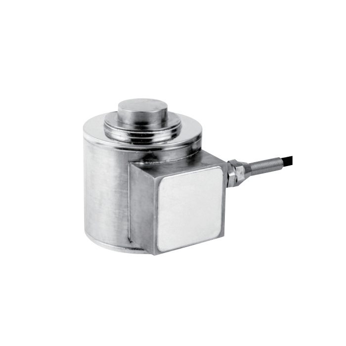
METRAVON MV-LC0180 is a compression load cell for hopper, silo and test-machine supports, offered at 20, 25, 30, 40, 50, 60, 70, 100, 150, 200, 300 and 400 t. Its contact and locating geometry change across the capacity range. An existing support needs a complete dimensional comparison before a higher-capacity sensor is selected.
Compare compression load cell contacts, not body height alone
The 100 t and 150 t rows both give body diameter A = 165 mm and overall height B = 184 mm, but lower locating diameter H changes from 70 to 78 mm. At 200 t and 300-400 t, A and B remain 233 and 250 mm, while upper contact diameter G changes from 100 to 108 mm. A shared body envelope is therefore not a complete compatibility check. Use the selected drawing to approve the upper contact, lower support and any locating features.
Lay out the cable route before enclosing the supports
The four-core cable note explicitly gives 12 m at 20 t, 14 m at 25-40 t and 20 m at 200-400 t. Confirm the delivered cable length for the 50-150 t group rather than relying on a length entry without a clear unit. Include reader location, junction positions and access for future service in the enquiry. The cable must remain protected without imposing a parasitic force on the loaded support.
Specify the reader and an achievable reference-loading method
The output is 2.0 +/-0.002 mV/V, with input resistance 385 +/-10 ohms and output resistance 350 +/-2 ohms. Check the measuring input and excitation capacity for the full installed bridge arrangement. Before completing the vessel or machine structure, agree how reference loading can be applied safely and repeated. Record the engineering units and verify the value at the final display or control-system channel after wiring and contact seating are complete.
| Item | Value | Selection notes |
|---|---|---|
| Capacity options | 20, 25, 30, 40, 50, 60, 70, 100, 150, 200, 300, 400 t | Specify the exact rating and associated dimensional row. |
| 20 t A / B | 76 / 82.6 mm | Use the full drawing for the contact and locating dimensions. |
| 25-40 t A / B | 100 / 117 mm | Review support clearances and the selected contact hardware. |
| 50-60 t A / B | 107 / 127 mm | Confirm the delivered cable length for this group. |
| 70 t A / B | 125 / 142 mm | A larger body does not establish a complete weighing module. |
| Excitation / temperature | 4-12 V DC / -30 to +70 deg C | Maximum excitation is 15 V DC; check actual site exposure. |
| Safe / ultimate overload | 150 / 200% FS | Review working reactions without treating overload as an operating allowance. |
Include structure and process effects in system acceptance
Determine the highest reaction at each measuring point under the intended operating states. Piping forces, restraints, uneven support stiffness and side contact can affect how load reaches the sensor. The sensor total-error entry is +/-0.05% FS and 30-minute creep is +/-0.02% FS, but neither establishes the complete installation result. Check repeated loading, unload return and any required hold condition with the actual support assembly.
For a 10-60 t column arrangement, compare MV-LC0174 with its own contact geometry and height groups instead of transferring this model's mounting dimensions.
Heavy-support replacement and scope
Q1. Will a 150 t unit fit a 100 t mounting because their envelopes match?
The listed A and B dimensions match, but the lower locating diameter differs. Compare all mating surfaces and restraints, then check the adjoining structure for the required force. The replacement cannot be approved from the outer diameter and height alone.
Q2. Does selecting 400 t provide a complete tank weighing module?
The compression sensor is only one part of the support. Contact pieces, restraint functions, uplift provisions, structure, measuring electronics and verification scope must be defined separately. Confirm those items in the assembly drawing and quotation rather than inferring them from the sensor capacity.
Q3. Can IP68 be used as a blanket approval for a flooded pit?
The entry does not identify an immersion depth or duration or cover every external electrical joint. Describe the water exposure and ask for the relevant test conditions for the ordered sensor. Review drainage, cable connections and enclosures as part of the installed system.
