


 Chinese
 Spanish
 Russian
 Portuguese
 French
 German
 Indonesian
 Thai
 Vietnamese
 Arabic
 Italian
 Turkish
 Polish
 Japanese



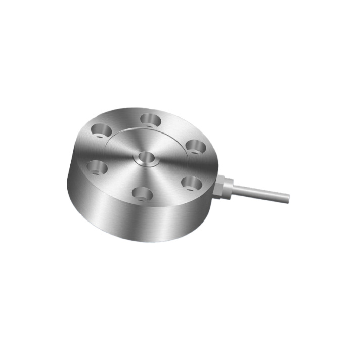
METRAVON MV-LC0179 is a low-profile flange load cell with a threaded centre and peripheral fixing holes. It lists 250 kg, 500 kg, 1, 2, 2.5, 3 and 5 t options for vessel weighing and force fixtures. The selected drawing must identify the centre connection and complete fixing pattern, rather than treating the capacity list as proof that every version shares the same body.
Check the low-profile flange load cell pattern at the selected rating
The 250-500 kg group gives outer diameter A = 75 mm, thickness B = 25 mm and a 57 mm fixing circle, with six holes and an M10 x 1.5 centre thread. The 5 t group changes to 140 mm diameter, 45 mm thickness, a 115 mm fixing circle, eight holes and M24 x 3. These are different assemblies. Review the fasteners, base stiffness and mating centre component together before reusing any part of an existing fixture.
| Item | Value | Selection notes |
|---|---|---|
| kg choices | 250, 500 kg | The lower group uses the documented six-hole arrangement. |
| t choices | 1, 2, 2.5, 3, 5 t | A listed rating still needs its matching version drawing. |
| 250-500 kg A / B | 75 / 25 mm | Check the 57 mm fixing circle and M10 x 1.5 centre thread. |
| 1-2.5 t A / B | 90 / 25 mm | Confirm fixing-circle and complete central-thread details. |
| 5 t A / B | 140 / 45 mm | The documented pattern has eight holes and M24 x 3. |
| Nominal sensitivity | 2.0 mV/V | Use confirmed output tolerance and individual calibration data. |
| Excitation / temperature | 4-12 V DC / -10 to +40 deg C | Maximum excitation is 15 V DC. |
Obtain the 3 t drawing before producing the mounting plate
The capacity list includes 3 t, but the dimensional rows identify 250-500 kg, 1-2.5 t and 5 t groups. A 3 t mounting should therefore be specified from a confirmed version drawing, not assigned to the nearest group. For the 1-2.5 t version, the listed outer diameter is 90 mm and thickness 25 mm, but the complete fixing circle and centre-thread details still need confirmation before manufacture.
Verify the threaded load introduction and channel setup
Define the intended force direction and how the central part transmits it into the sensing body. Tightening the centre attachment or fixing bolts can introduce preload or distortion, so obtain the appropriate assembly instructions and then record unloaded zero. Nominal sensitivity is 2.0 mV/V, input resistance 750 +/-30 ohms and output resistance 702 +/-2 ohms. Confirm actual sensitivity and the reader settings before calibration.
Set performance requirements for the installed fixture
Agree the smallest required force change, upper working load, repeated-loading behaviour and any hold duration. Obtain confirmed nonlinearity, creep and calibration documents for the ordered version rather than inferring them from a class entry. The listed working range is -10 to +40 deg C with steel options and IP67. Confirm the delivered cable length, construction and connection protection as part of the order.
Version drawings and mounting effects
Q1. Can the 3 t version be installed from the 1-2.5 t dimensions?
Not without a confirmed drawing for 3 t. That rating is listed, but it is not assigned to the shown dimensional group. Identify the exact version and resolve centre thread, fixing circle, holes and clearance before machining or approving the support.
Q2. Does a flat base eliminate errors from mounting?
A low profile does not remove sensitivity to an uneven base, unsuitable contact or fastening distortion. Review the support stiffness and specified bolt arrangement. Inspect the assembled zero, then compare repeated reference loads after the complete centre attachment and cable support are installed.
Q3. What should a replacement quotation include?
Provide the original sensor drawing, centre thread, fixing pattern, installed height and rated load. Add force direction, preload, loading cycle, temperature and measuring electronics. Request confirmed performance and calibration information for the offered version so acceptance is based on the real fixture.
