


 Chinese
 Spanish
 Russian
 Portuguese
 French
 German
 Indonesian
 Thai
 Vietnamese
 Arabic
 Italian
 Turkish
 Polish
 Japanese



METRAVON MV-LC0178 is a flange compression load cell with a recessed central contact and nominal 4 mV/V output. Ratings are listed as 5, 10, 25, 50 and 100 klb, or 2.5, 5, 10, 25 and 50 t. The electrical signal is larger than that of a nominal 2 mV/V bridge, making reader range and calibration important checks when replacing an existing sensor.
Check whether the reader accepts a 4 mV/V bridge
With 10 V excitation, nominal rated-load output is about 40 mV, compared with 20 mV from a 2 mV/V bridge at the same excitation. Check the input range and allow for the actual rated output and zero balance. Do not retain the old gain or span without verification. Input resistance is 385 +/-10 ohms and output resistance 350 +/-2 ohms; obtain the delivered sensitivity tolerance and calibration data before final channel setup.
Flange compression load cell mounting needs the mating contact profile
The central recess and surrounding flange define a different load path from a threaded-centre sensor. Submit the actual loading component, contact shape and flange fastening arrangement for review. The metric 2.5-5 t row gives outer diameter D = 104.6 mm and height H = 44.5 mm; 10-25 t gives 120.7 and 53.8 mm; 50 t gives 139.7 and 57.2 mm. These outside dimensions are only part of the fit check, not permission to substitute an arbitrary contact ball or adapter.
| Item | Value | Selection notes |
|---|---|---|
| klb options | 5, 10, 25, 50, 100 klb | Order against the selected imperial configuration drawing. |
| t options | 2.5, 5, 10, 25, 50 t | Keep the metric rating and dimensional row together. |
| Nominal output | 4.0 mV/V | Check the input headroom before using an existing 2 mV/V setup. |
| 2.5-5 t D / H | 104.6 / 44.5 mm | Confirm the recessed contact and fixing pattern. |
| 10-25 t D / H | 120.7 / 53.8 mm | Use the complete drawing for all mating parts. |
| 50 t D / H | 139.7 / 57.2 mm | A larger rating changes the flange envelope. |
| Excitation / protection | 4-12 V DC; IP67 | Maximum excitation is 15 V DC; confirm material and cable details. |
Keep the chosen rating and drawing units explicit
The capacity list contains separate imperial and metric options. Obtain a unit-confirmed drawing for the selected klb or t version before machining the base or fixing pattern. Do not mix dimensions from different rows or regard their nominal rating labels as exact unit conversions. Check contact, bolt-circle, hole and counterbore geometry together with the available electrical-cable access.
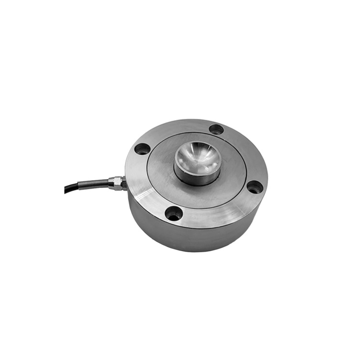
Agree the held-load and cyclic checks before acceptance
The listed nonlinearity and hysteresis are each +/-0.03% FS. They do not define complete fixture accuracy or establish performance during every loading cycle. Obtain confirmed creep data for the required load-hold duration and record reference loading, unloading and repeat readings with the final contacts installed. Working temperature is -10 to +40 deg C; verify it at the sensor when the fixture is near a warm process.
Where a threaded centre and square base are required, review MV-LC0177 separately; its load interface and nominal 2 mV/V output are different.
Input range and configuration checks
Q1. Can the amplifier used with a 2 mV/V sensor remain unchanged?
It may be usable only if its excitation, input range and calibration adjustment support the new 4 mV/V bridge. Compare the actual instrument specifications and verify the complete channel with reference loading. A gain setting that suited the old sensor can overrange or mis-scale the new signal.
Q2. Are the t ratings exact conversions of the klb options?
These are separate nominal capacity options, not exact unit conversions. Specify the ordered rating in klb or t, use its matching drawing, and calibrate the installed channel against reference loads in the required engineering units. Do not approve a mechanical replacement until the rating and drawing units are confirmed.
Q3. Which cable length is standard?
The model table does not establish one. Provide the connection route, required termination and reader position, then obtain the delivered cable configuration on the offer. No cable length or connector should be assumed from an adjacent flange model.
