


 Chinese
 Spanish
 Russian
 Portuguese
 French
 German
 Indonesian
 Thai
 Vietnamese
 Arabic
 Italian
 Turkish
 Polish
 Japanese



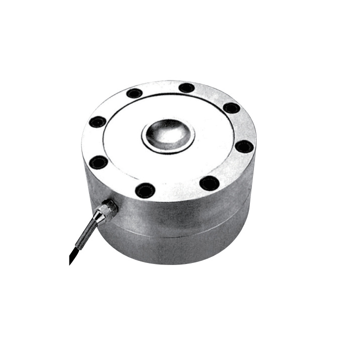
METRAVON MV-LC0175 is a compression load cell offered at 10, 20, 25, 30 and 40 t for hopper, silo and test-machine installations. Its circular body works with the specified central load-head arrangement. The sensor body height and the complete height with a load head are different dimensions, which matters when replacing a support beneath an existing vessel.
Allow space for the compression load cell and its head
The drawing identifies H3 as the body height and H4 as the height with the illustrated load head. The head's thread changes with capacity. Use the installed assembly dimension when planning clearance, and ask the quotation to identify whether the head and mating parts are included.
| Rating | Body H3 | With head H4 | Thread M |
|---|---|---|---|
| 10 t | 74 mm | 134.5 mm | M20 x 1.5 |
| 20, 25 t | 87 mm | 171 mm | M24 x 1.5 |
| 30 t | 86 mm | 176 mm | M30 x 1.5 |
| 40 t | 95.8 mm | 221 mm | M40 x 1.5 |
For vessel retrofits, compare the old support height with H4, not just H3. Changing the height can also change pipe restraint and load distribution among the supports. The mounting design should accommodate the intended load transfer and vessel movement without relying on the sensor to act as a lateral stop.
3 mV/V output and rated-load options
| Item | Value |
|---|---|
| Output sensitivity | 3.0 ±0.006 mV/V |
| Total error | ±0.05% FS |
| 30-minute creep | ±0.05% FS |
| Input / output resistance | 385 ±10 / 351 ±2 ohm |
| Excitation range | 4-12 V DC; maximum 15 V DC |
| Operating temperature | -30 to +70 °C |
| Safe overload / protection | 150% FS / IP67 |
| Standard cable, 10-25 t | 12 m, 5 mm diameter |
| Standard cable, 30-40 t | 16 m, 5 mm diameter |
A replacement must match the electrical design as well as the support. If the existing scale uses a different sensitivity or resistance, review the sensor set and junction-box connections before selecting a single replacement. Recalibration is required after a change; a matching connector is not evidence of an equivalent signal.
Separate weighing performance from structural protection
Calculate the greatest compression at each support during the relevant loading cases. For a hopper, filling impact and an uneven material distribution can matter as much as the steady material weight. For a test machine, include tooling preload and the maximum force transmitted through the sensing position.
The safe-overload figure does not authorize routine operation above the selected rating. Uplift restraints, side-load limits and anti-overturning features belong to the assessed mounting assembly. Where these are required, submit the vessel support drawing for a module review rather than treating the bare sensor as a complete support system.
Questions for an existing vessel installation
Q1. Does the 30 t version have the same installed height as the 25 t version?
No. Although the listed body heights are close, the height with the illustrated head changes from 171 to 176 mm and the head thread changes from M24 x 1.5 to M30 x 1.5. Check the complete assembly rather than inferring interchangeability from a photograph.
Q2. What should acceptance testing include after replacement?
Record the empty-vessel zero after reconnecting permanent pipework, compare readings at agreed reference loads and repeat after unloading. Inspect each support for proper seating. A span adjustment should not be used to conceal a support that is bound by a pipe or restraint.
Request MV-LC0175 with the required load-head assembly. Include the old installed height, maximum support reaction, instrument model and cable route, and state whether the enquiry is for a bare sensor or a complete mounting arrangement.
