


 Chinese
 Spanish
 Russian
 Portuguese
 French
 German
 Indonesian
 Thai
 Vietnamese
 Arabic
 Italian
 Turkish
 Polish
 Japanese



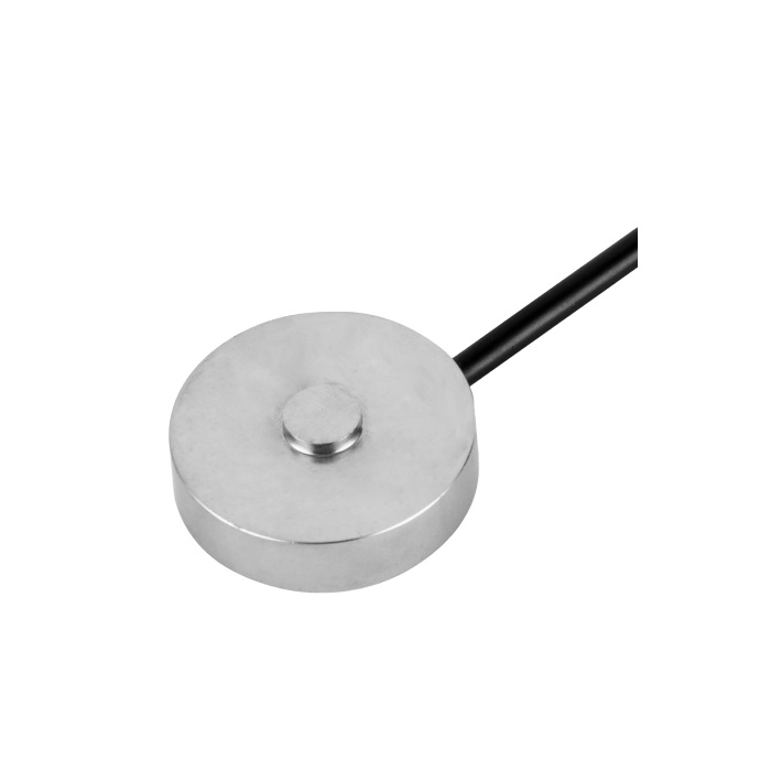
METRAVON MV-LC0173 is a miniature compression load cell with a raised central contact and three fixing positions spaced at 120 degrees. It is offered at 200 and 500 lb or 1, 2, 3 and 5 klb. The stainless-steel body provides a compact force-measuring element, but the small envelope should not be mistaken for a particular system-accuracy class.
Keep the miniature compression load cell rating in lb or klb
The 200 lb-2 klb group has a 32 mm outer diameter, 25.4 mm fixing circle and 10 mm height dimension H. At 3-5 klb these become 38, 31.4 and 16 mm. The contact diameter also increases from 8.1 to 11 mm. A replacement selected only by its load number can therefore have the wrong units, fixing circle and contact. Confirm the complete drawing and available stack height for the chosen version.
| Item | Value | Selection notes |
|---|---|---|
| Lower capacity choices | 200, 500 lb | The numerical values are not kilogram ratings. |
| Higher capacity choices | 1, 2, 3, 5 klb | One klb denotes one thousand pounds. |
| 200 lb-2 klb diameter / H | 32 / 10 mm | Fixing circle is 25.4 mm; contact diameter is 8.1 mm. |
| 3-5 klb diameter / H | 38 / 16 mm | Fixing circle is 31.4 mm; contact diameter is 11 mm. |
| Fixing thread | Three #6-32 UNC positions | Obtain the full drawing and engagement instructions. |
| Excitation | 4-12 V DC; maximum 15 V DC | Select a compatible bridge input, not a voltage-signal input. |
| Working temperature | -30 to +70 deg C | No standard cable length is established in the model table. |
Use the specified UNC fixings and a reviewed contact
The fixing designation is #6-32 UNC, not a metric thread of a similar diameter. Use the correct mating fasteners and obtain the permitted engagement and tightening instructions. The drawing identifies a spherical contact radius SR35; that geometry does not specify an allowable side-load angle or unrestricted tilting joint. The mating component still needs a stable axial load path, with enough clearance to prevent the body or cable becoming a second contact.
Obtain the ordered sensitivity before selecting amplifier gain
The listed output range is 0.5-1.0 mV/V, without an assignment of one sensitivity to each capacity. At 10 V excitation, that represents a nominal rated-signal range of 5-10 mV; it is not a guarantee of one value for every unit. Confirm actual rated output and calibrate the completed measuring channel. Input resistance is 350 +/-5 ohms and output resistance 350 +/-2 ohms. Keep signal units distinct from a 0.5-1.0 V conditioned output.
Set acceptance limits that reflect the required force measurement
The total-error entry is +/-0.5% FS and 30-minute creep is +/-0.03% FS. A percentage of full scale is not the same as a percentage of each reading, particularly near the bottom of the range. Choose capacity, reader resolution and reference-loading points from the smallest useful force change as well as the peak load. Check repeated loading and the unloaded return after the contact and fasteners are in their final configuration.
Fasteners, sensitivity and contact geometry
Q1. Can an M3 screw be used if it appears to fit?
No substitution should be made from appearance. The specified thread is #6-32 UNC, with a different diameter and pitch from metric fasteners. Confirm the mating thread and engagement before assembly; forcing a near-sized screw can damage the fixing and compromise the installation.
Q2. Does every 5 klb version provide 1 mV/V?
The specification gives a 0.5-1.0 mV/V range but does not allocate the endpoints by capacity. Request the rated output of the offered unit and its calibration information. Set the amplifier gain and span from those data rather than assigning a value from the load rating.
Q3. Does the spherical button allow the fixture to tilt freely?
The listed radius describes the contact surface, not an articulated joint or permitted angular travel. Review the opposing contact, alignment and restraints as a complete mechanical arrangement. Keep unintended bending and side contact out of the compression measurement.
