


 Chinese
 Spanish
 Russian
 Portuguese
 French
 German
 Indonesian
 Thai
 Vietnamese
 Arabic
 Italian
 Turkish
 Polish
 Japanese



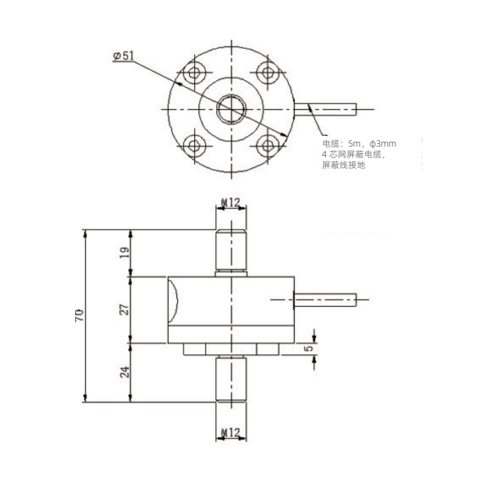
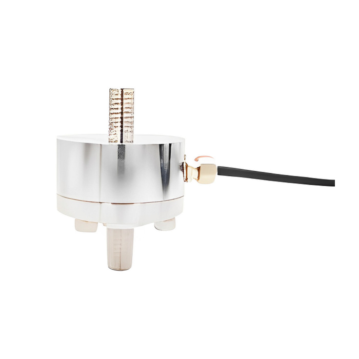
METRAVON MV-LC0171 is a low-profile tension and compression force sensor for press equipment and bidirectional force-testing fixtures. It offers 500 N and 1, 2, 5, 10, 20, 30 and 50 kN ratings. Threaded attachments at both ends carry axial force; the fixture must keep bending and side forces from becoming part of the measurement.
Review the tension and compression force sensor with both end fittings
The drawing gives a 51 mm flange diameter, 27 mm central-body height and 70 mm overall end-to-end dimension. Both end attachments are marked M12, but the pitch is not specified. Check the actual mating thread, engagement, locking method and clearance through the full machine travel. Do not machine the mating parts from the nominal M12 designation alone or use the cable exit as an anti-rotation feature.
Distinguish rated sensitivity tolerance from measurement error
Nominal rated output is 1 mV/V, with sensitivity allowed to vary by +/-10%. That tolerance describes the signal at rated force; it does not mean that measured force necessarily has a +/-10% error after calibration. Nonlinearity, hysteresis and repeatability are each listed as +/-0.1% of nominal force Cn. Use the individual calibration result to scale the channel and agree a separate acceptance requirement for the completed fixture.
| Item | Value | Selection notes |
|---|---|---|
| Lower force option | 500 N | Keep newtons explicit in the order and display configuration. |
| Higher force options | 1, 2, 5, 10, 20, 30, 50 kN | Select from peak axial force in the intended loading cycle. |
| Nominal sensitivity | 1 mV/V; +/-10% tolerance | Calibrate from the actual sensitivity rather than a nominal span. |
| Flange / body / overall length | 51 / 27 / 70 mm | These dimensions describe different parts of the assembly. |
| Reference / working excitation | 5 V / 1-15 V | A 24 V supply must not be connected directly to the bridge. |
| Construction / protection | Stainless steel / IP66 | No IP67 immersion rating is stated for this model. |
Supply bridge excitation, not an ordinary 24 V field connection
The reference excitation is 5 V, and the stated operating range is 1-15 V. Input resistance is 350 +/-30 ohms and output resistance 350 +/-3 ohms. A four-core braided-shield cable is listed at 5 m long and 3 mm diameter. Use a suitable bridge amplifier or weighing input; if the control system needs 4-20 mA or RS485, specify that interface at the conditioning stage instead of assuming it is built into the sensor.
Validate each force direction and the actual temperature
Record zero, tensile reference loads, compressive reference loads and the unloaded return after the attachments are secured. A calibration performed in only one direction does not verify the opposite direction of the installed fixture. The nominal temperature range is -10 to +40 deg C, service range -10 to +50 deg C and storage range -25 to +70 deg C. Storage limits do not permit operation, and the wider service limit should not be treated as a guarantee of nominal performance throughout.
Calibration direction and temperature limits
Q1. Does the +/-10% output tolerance make the sensor unsuitable for accurate testing?
It means different units can produce different rated signals within the stated tolerance. A compatible reader can be calibrated for the actual unit, but the required force accuracy still depends on calibration evidence, other sensor errors and the fixture. Define the permissible installed error and test it over the required force range.
Q2. Can one zero and span check cover tension and compression?
Not by itself. Test the reference points and return behaviour needed in each working direction, using the assembled end fittings. Record the sign convention in the final control channel so a tensile reading cannot be mistaken for compression.
Q3. Is operation at +70 deg C permitted?
That value is the storage upper limit. The documented service upper limit is +50 deg C, with a narrower nominal temperature range ending at +40 deg C. Describe the sensor temperature during the machine cycle before accepting an installation near heated tooling.
