


 Chinese
 Spanish
 Russian
 Portuguese
 French
 German
 Indonesian
 Thai
 Vietnamese
 Arabic
 Italian
 Turkish
 Polish
 Japanese



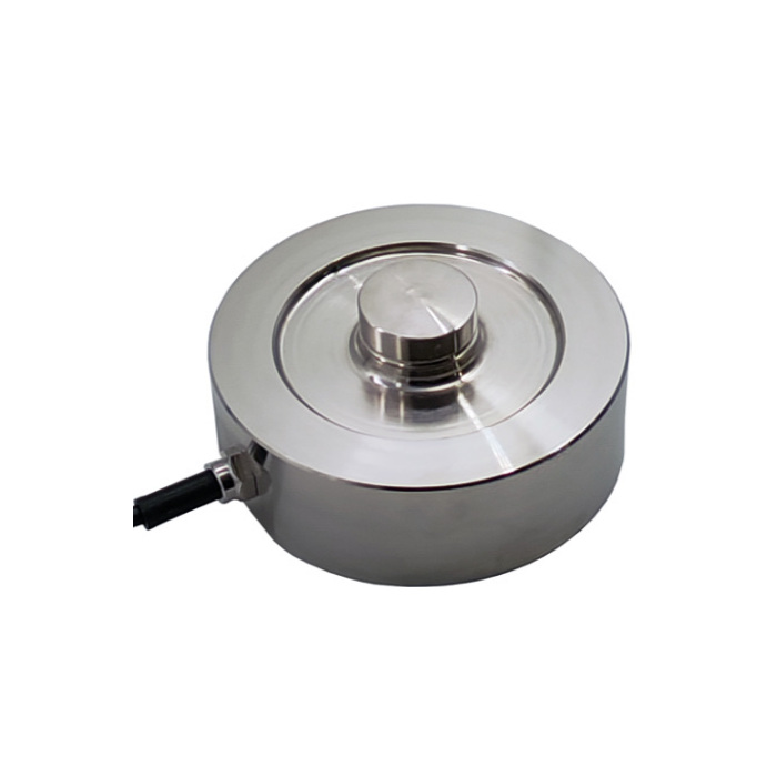
METRAVON MV-LC0170 is a low-profile compression button load cell for fixtures that apply force to a central contact. Rated-load options are 50, 100, 250, 500 and 1000 kg. Its round body and raised loading button suit a compact compression stack; it is not a beam that is fixed at one end and loaded at the other.
Fit the button load cell into the compression stack
| Drawing feature | Dimension |
|---|---|
| Body diameter | 52 mm |
| Overall height / body height | 22 / 18 mm |
| Loading-button diameter | 10 mm |
| Mounting pattern | Four M5 x 0.8 holes |
| Hole depth / pitch-circle diameter | 8 / 44 mm |
Check the available space with the load platen and base plate included. The platen should contact the intended central button without touching the surrounding body. Mounting screw length must suit the 8 mm hole depth and the thickness of the mating plate; a screw that bottoms out can give a false impression of a securely clamped base.
Choose capacity against the force you need to distinguish
The published non-linearity is ±0.3% FS. For a 100 kg-rated version, 0.3% of full scale corresponds to 0.3 kg of rated-load equivalent. It does not mean 0.3% of every reading, and it is not a complete uncertainty statement for the test fixture. A high-capacity sensor may be unsuitable when the useful measurement is a small change near the bottom of its range.
| Measurement characteristic | Specification |
|---|---|
| Rated sensitivity | 2.0 ±0.002 mV/V |
| Non-linearity | ±0.3% FS |
| Creep over 30 minutes | ±0.3% FS |
| Input / output resistance | 750 ±10 / 700 ±2 ohm |
| Excitation | 4-12 V DC; maximum 15 V DC |
| Operating temperature | -10 to +40 °C |
| Safe overload / protection | 150% FS / IP67 |
Specify whether the task is a short compression check or a held load. For a hold test, assess the permitted change in indication during the hold as well as the initial reading. Do not interpret the 30-minute creep value as a sampling speed, response time or a limit established for every possible dwell duration.
Build the acquisition and acceptance test around the fixture
Connect the sensor to a bridge-input amplifier or weighing instrument. A PLC input expecting volts or milliamps cannot be selected from the mV/V value alone. For peak-force capture, agree the required recording interval and filtering with the instrument supplier; no bandwidth is specified here.
Check the unloaded reading after fastening the sensor, then apply a reference force through the same contact used in production. Test at the working loads, unload and repeat. If the reading depends strongly on where the platen contacts the button, correct the contact geometry before calibrating. Temperature at the sensor must stay within the stated operating range, even if the surrounding machine operates hotter.
Fixture questions
Q1. Can the base mounting holes be used to measure tension?
The holes locate and secure the body. They do not establish a tensile measurement arrangement or tensile load rating. Use this model for the defined compression contact, and select a separately documented tension-capable sensor for pulling tests.
Q2. Should the highest capacity be chosen to protect against a press crash?
Capacity selection cannot replace an engineered travel stop or machine protection. Define the normal force, credible peak and smallest required measurement change. Check the stop arrangement separately so an abnormal stroke is not simply passed into the sensor.
Send an MV-LC0170 fixture enquiry with a section through the platen and base, expected force range, hold time, sensor temperature and required recording behaviour. These details determine whether this compact geometry and error specification meet the test.
