


 Chinese
 Spanish
 Russian
 Portuguese
 French
 German
 Indonesian
 Thai
 Vietnamese
 Arabic
 Italian
 Turkish
 Polish
 Japanese



METRAVON MV-LC0168 is a button compression load cell for hopper, silo and weighing-module assemblies. A central raised button introduces the compressive load into a cylindrical body. Choose from 250 and 500 kg or 1, 2.5, 5, 7.5, 10, 15, 30, 50 and 100 t ratings; the selected capacity determines the contact dimensions and cable group.
Support the button compression load cell without bypassing it
The base needs a suitable bearing surface, while the upper loading component must seat on the intended button contact. Check the contact profile, support stiffness and axial force direction together. A surrounding stop, restraint or pipe connection can divert part of the vessel load away from the sensor. Specify lateral restraint and uplift protection at assembly level; the compression element alone does not provide those module functions.
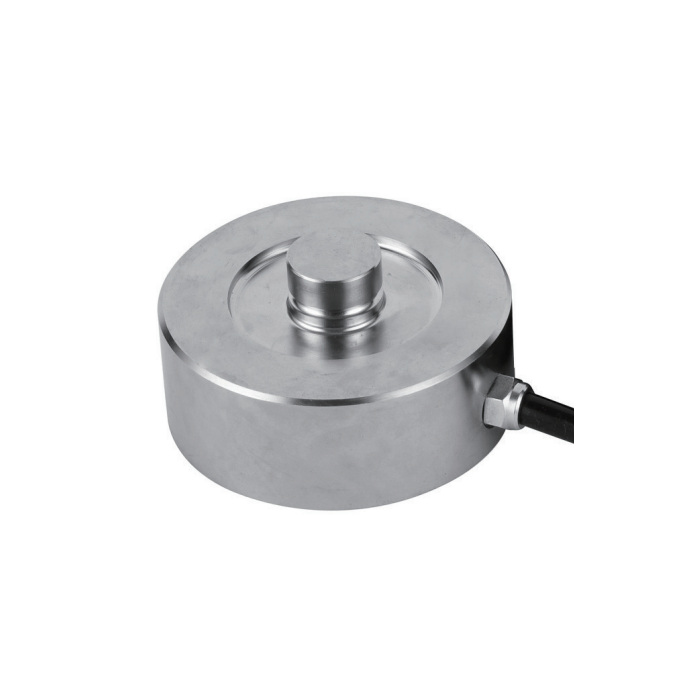
Match contact diameter and height to the selected capacity
The 250 kg-10 t group shares an 82 mm body diameter and 44 mm overall height, but equal dimensions do not make the ratings interchangeable. The 15 t version changes to 100 mm diameter and 48.5 mm height; 30 t uses 126 and 54 mm; 50-100 t uses 165 and 80 mm. Button contact diameters for those four groups are 22, 28, 35 and 60 mm respectively. Check both mating parts before retaining an existing support.
| Item | Value | Selection notes |
|---|---|---|
| Lower ratings | 250, 500 kg | These options share the lower dimensional group. |
| Tonne ratings | 1, 2.5, 5, 7.5, 10, 15, 30, 50, 100 t | There is no 2 t option in this model list. |
| 250 kg-10 t diameter / height | 82 / 44 mm | The button contact diameter is 22 mm. |
| 15 t diameter / height | 100 / 48.5 mm | The button contact diameter increases to 28 mm. |
| 30 t diameter / height | 126 / 54 mm | Review the 35 mm button and adjoining support. |
| 50-100 t diameter / height | 165 / 80 mm | Confirm the 60 mm contact diameter and available clearance. |
| Working temperature | -30 to +70 deg C | Assess exposure at the sensor and cable termination. |
Place the reader within the correct cable allowance
The listed four-core cable is 5 m for 250 kg-10 t and 10 m for 15-100 t, with a 5 mm cable diameter. The bridge delivers 2.0 +/-0.002 mV/V, with 750 +/-10 ohms input resistance and 702 +/-2 ohms output resistance. Select a weighing indicator or bridge conditioner that supplies suitable excitation and reads the millivolt signal. A PLC input expecting a current loop cannot read this raw bridge directly.
Test the vessel with piping and restraints in their operating positions
Size each support from its highest expected reaction, including vessel tare, contents and relevant process forces, rather than dividing contents alone by the number of supports. After seating the contacts, compare repeated reference loads and the return to empty. Observe whether filling, discharge or pipe movement changes the reading independently of material weight. Listed total error is +/-0.05% FS and 30-minute creep is +/-0.02% FS; these sensor figures do not establish complete vessel accuracy.
Support reuse and water exposure
Q1. Can the same mounting accept every rating below 10 t?
The published outer dimensions are shared, but capacity, calibration and the structural adequacy of the mating parts still require verification. Obtain the selected rating on the drawing and quotation. Increasing the sensor rating does not increase the allowable load of the vessel frame or contact hardware.
Q2. Does the IP68 entry permit permanent submersion?
Depth, duration and termination conditions are not specified by the model entry. Describe flooding or washdown exposure and obtain the applicable test conditions for the offered construction. Review external cable joints and enclosures separately.
