


 Chinese
 Spanish
 Russian
 Portuguese
 French
 German
 Indonesian
 Thai
 Vietnamese
 Arabic
 Italian
 Turkish
 Polish
 Japanese



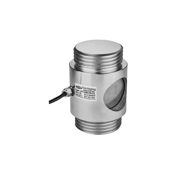
METRAVON MV-LC0167 is a threaded cylindrical load cell listed for hopper, silo and weighing-module arrangements at 10, 20, 30 and 40 t. External threads at the ends create a different mechanical connection from a freely seated button sensor. The enquiry should identify how the assembly introduces force and whether the documented offered configuration supports that intended loading direction.
Approve the threaded cylindrical load cell with its mating components
The reference drawing shows M80 x 6 threads, a 95 mm body diameter and a 150 mm end-to-end length, with a 30 mm threaded-end length callout. Obtain the complete end details and permitted engagement before manufacturing the mating parts. Compare shoulders, locking arrangement, cable access and surrounding clearances as well as the nominal thread. A similar outside diameter is not evidence that a different pitch or attachment can be used safely.
| Item | Value | Selection notes |
|---|---|---|
| Capacity choices | 10, 20, 30, 40 t | Confirm the intended load direction for the ordered configuration. |
| External thread | M80 x 6 | Review the full mating drawing and approved engagement. |
| Body diameter / overall length | 95 / 150 mm | Keep room for the side connection and installation tools. |
| Nominal rated output | 2.0 +/-0.002 mV/V | Calibrate with the final attachments in place. |
| Excitation | 4-12 V DC; maximum 15 V DC | Check the reader and the complete connected bridge load. |
| Working temperature | -10 to +40 deg C | Do not substitute temperature limits from a different model. |
| Cable configuration | Confirm length and termination | No standard cable length is established in the model table. |
Specify the force path rather than inferring bidirectional performance
Two threaded ends do not by themselves establish a rated tension-and-compression calibration. State the force direction, assembly preload, working range and any reversal in the machine cycle, then request the corresponding confirmation for the offered version. Align the adjoining components so the intended force reaches the sensing body without bending from a rigidly offset connection. Do not use the cable gland or exposed body as an improvised installation tool.
Check the 700 ohm bridge and recalibrate after assembly
Rated output is 2.0 +/-0.002 mV/V, with 700 +/-10 ohms input resistance and 700 +/-2 ohms output resistance. Match the excitation supply and measuring input to that bridge rather than carrying over a nominal-output setting alone. Finish the mechanical fastening procedure before setting zero, then apply the agreed reference loads through the installed connections. Record the resulting scale factor and return behaviour at the channel used by the operator.
Use the documented temperature and performance boundaries
Working temperature is -10 to +40 deg C, narrower than the -30 to +70 deg C range shown for some other cylindrical weighing sensors. Nonlinearity is +/-0.1% FS and 30-minute creep +/-0.03% FS; nonlinearity is not a total-system accuracy statement. The D1 class entry is not proof of whole-machine approval. For outdoor or warm-process installations, establish the actual sensor temperature and connection protection before accepting the proposed arrangement.
Thread matching and load-direction confirmation
Q1. Do the two external threads prove that it measures pulling and pushing equally?
No. A threaded connection describes the attachment, not the verified loading directions or calibration scope. Submit the actual force cycle and obtain confirmation for the ordered configuration. If force reverses, acceptance must cover the required direction-specific reference points.
Q2. Can an existing mating part be approved from M80 alone?
The documented interface is M80 x 6, and engagement, shoulders and locking details also matter. Obtain the mating drawing and compare the full connection before assembly. A shared nominal diameter without the correct pitch and load-bearing geometry is insufficient.
Q3. What should accompany a replacement enquiry?
Send the original sensor and mating-part drawings, installed length, capacity and force direction. Add preload, load cycle, reader details, operating temperature and the required cable route. Identify whether both adjoining parts can be inspected before reuse so worn or mismatched connections are not hidden by the sensor change.
