


 Chinese
 Spanish
 Russian
 Portuguese
 French
 German
 Indonesian
 Thai
 Vietnamese
 Arabic
 Italian
 Turkish
 Polish
 Japanese



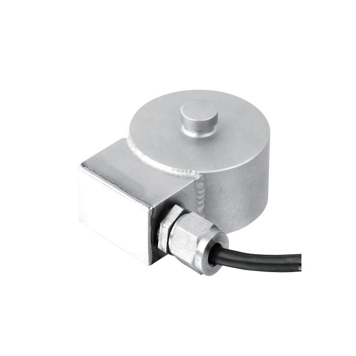
METRAVON MV-LC0166 is a button compression load cell with four threaded fixing positions and a side cable housing. It offers 50, 100, 200 and 500 kg plus 1, 2, 5, 10, 20, 30 and 50 t ratings. Four dimensional groups define different body diameters, contact buttons and fixing arrangements; specify the selected rating rather than only the model family.
Match the button compression load cell to the full fixing pattern
For 50 kg-1 t, the reference body diameter A is 50 mm, height B is 30 mm, fixing-circle diameter C is 42 mm and the four threads are M5. At 2-5 t these change to 90, 48 and 70 mm with M10 threads. At 10-20 t the corresponding values are 115, 60 and 90 mm with M12; at 30-50 t they are 155, 90 and 125 mm with M16. Compare the entire row before reusing a base plate.
Keep fastening forces separate from the measuring contact
The central button transfers the measured compression while the fixing pattern locates the sensor. Provide the opposing contact profile, support stiffness and intended fastening arrangement. Obtain screw engagement and tightening instructions rather than borrowing a torque from another size. Clearance around the side housing and cable is needed for assembly and service. Check unloaded zero after fastening, then verify that surrounding restraints do not touch the loaded components during operation.
Select the range with the stated error and useful signal in mind
Published total error is +/-0.3% FS, not +/-0.03% FS. The 30-minute creep entry is +/-0.05% FS, and rated sensitivity is 2.0 +/-0.05 mV/V. These figures matter when comparing low-force resolution or replacing a higher-accuracy channel. Define the smallest force change the system must resolve and verify it at suitable reference points; a higher capacity or nominal 2 mV/V label alone does not establish equivalent measurement performance.
| Item | Value | Selection notes |
|---|---|---|
| kg options | 50, 100, 200, 500 kg | The lower group uses M5 fixings and a 13 mm button diameter. |
| t options | 1, 2, 5, 10, 20, 30, 50 t | Choose only from the discrete listed capacities. |
| 2-5 t button / fixing circle | 25 / 70 mm | Four M10 positions differ from the lower group. |
| 10-20 t button / fixing circle | 32 / 90 mm | Check the M12 connection and complete row. |
| 30-50 t button / fixing circle | 44 / 125 mm | This group uses M16 threads and a 155 mm body. |
| Total error / 30-minute creep | +/-0.3 / +/-0.05% FS | Do not infer a tighter class from a neighbouring button model. |
| Excitation / temperature | 4-12 V DC / -30 to +70 deg C | Maximum excitation is 15 V DC. |
Choose the cable group and confirm the final system reading
The four-core lead is 3 m at 50 kg-1 t, 6 m at 2-5 t and 12 m at 10-50 t; cable diameter is 5 mm. Bridge input and output resistances are 385 +/-10 and 350 +/-2 ohms respectively. Check excitation loading for all connected sensors, finish the cable terminations and establish the final zero and span. Compare loading and unloading readings at the actual display or control input, not only at a temporary bench instrument.
Capacity changes and measurement limits
Q1. Can the 5 t sensor use the base plate from a 1 t version?
The documented fixing circle, thread size, body diameter and height differ. Check the 2-5 t dimensional row against the base, upper contact and available space. The old plate is not an automatic fit simply because both units share the MV-LC0166 designation.
Q2. Does +/-0.3% FS mean +/-0.3% of every reading?
FS refers to the selected full-scale capacity, not the current reading. Its significance relative to the measured load increases toward the lower end. Assess the required measurement interval and installed uncertainty before choosing a large-capacity version for a small normal load.
Q3. Can IP68 substitute for specifying the cable-joint protection?
The complete installation still needs suitable joints, routing and enclosures. Describe water exposure and obtain the relevant conditions for the offered sensor construction. Do not assume that a field splice gains the sensor housing rating.
